doc00006
advertisement

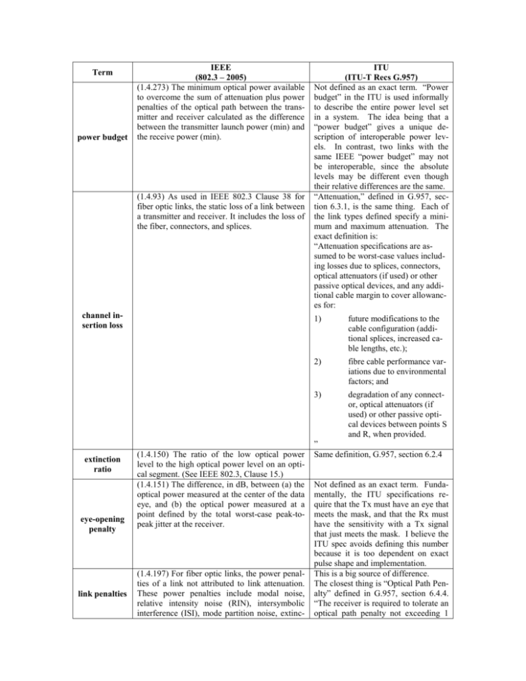
Term power budget IEEE (802.3 – 2005) (1.4.273) The minimum optical power available to overcome the sum of attenuation plus power penalties of the optical path between the transmitter and receiver calculated as the difference between the transmitter launch power (min) and the receive power (min). (1.4.93) As used in IEEE 802.3 Clause 38 for fiber optic links, the static loss of a link between a transmitter and receiver. It includes the loss of the fiber, connectors, and splices. channel insertion loss extinction ratio eye-opening penalty link penalties (1.4.150) The ratio of the low optical power level to the high optical power level on an optical segment. (See IEEE 802.3, Clause 15.) (1.4.151) The difference, in dB, between (a) the optical power measured at the center of the data eye, and (b) the optical power measured at a point defined by the total worst-case peak-topeak jitter at the receiver. (1.4.197) For fiber optic links, the power penalties of a link not attributed to link attenuation. These power penalties include modal noise, relative intensity noise (RIN), intersymbolic interference (ISI), mode partition noise, extinc- ITU (ITU-T Recs G.957) Not defined as an exact term. “Power budget” in the ITU is used informally to describe the entire power level set in a system. The idea being that a “power budget” gives a unique description of interoperable power levels. In contrast, two links with the same IEEE “power budget” may not be interoperable, since the absolute levels may be different even though their relative differences are the same. “Attenuation,” defined in G.957, section 6.3.1, is the same thing. Each of the link types defined specify a minimum and maximum attenuation. The exact definition is: “Attenuation specifications are assumed to be worst-case values including losses due to splices, connectors, optical attenuators (if used) or other passive optical devices, and any additional cable margin to cover allowances for: 1) future modifications to the cable configuration (additional splices, increased cable lengths, etc.); 2) fibre cable performance variations due to environmental factors; and 3) degradation of any connector, optical attenuators (if used) or other passive optical devices between points S and R, when provided. ” Same definition, G.957, section 6.2.4 Not defined as an exact term. Fundamentally, the ITU specifications require that the Tx must have an eye that meets the mask, and that the Rx must have the sensitivity with a Tx signal that just meets the mask. I believe the ITU spec avoids defining this number because it is too dependent on exact pulse shape and implementation. This is a big source of difference. The closest thing is “Optical Path Penalty” defined in G.957, section 6.4.4. “The receiver is required to tolerate an optical path penalty not exceeding 1 tion ratio, and eye-opening penalties. dB (2 dB for L-16.2) to account for total degradations due to reflections, intersymbol interference, mode partition noise, and laser chirp.” Fundamentally, the ITU definition focuses on the penalty that is caused by going over the optical path, as opposed to just pure attenuation. This definition differs from the IEEE definition in that it does not include RIN, extinction ratio, eye-opening penalties, and, to some extent, ISI, if that ISI is electronic in nature, and not as a result of fiber dispersion. Those are pretty significant differences. In the ITU method, these impairments are accounted for in the specification of the Tx and Rx values. In contrast, the IEEE Tx and Rx values are more of an ‘ideal case’ number, to which the above impairments are deducted. Of course, the final result is much the same. It is just the way that the impairments are grouped together.


