Origins and limitations of photonic bandgap fibres
advertisement
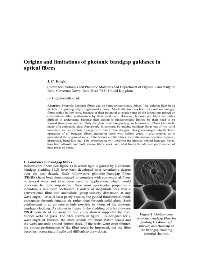
Origins and limitations of photonic bandgap guidance in optical fibres J. C. Knight Centre for Photonics and Photonic Materials and Department of Physics, University of Bath, Claverton Down, Bath, BA2 7AY, United Kingdom j.c.knight@bath.ac.uk Abstract. Photonic bandgap fibres can do some extraordinary things, like guiding light in an air hole, or guiding only a higher-order mode. Much attention has been focussed on bandgap fibres with a hollow core, because of their potential to evade some of the limitations placed on conventional fibre performance by their solid core. However, hollow-core fibres are rather difficult to understand, because their design is fundamentally limited by their need to be formed from glass and air. Only the glass is self-supporting, so hollow-core fibres have to be made of a connected glass framework. In contrast, by making bandgap fibres out of two solid materials, we can explore a range of different fibre designs. This gives insight into the basic operation of all bandgap fibres, including those with hollow cores. It also enables us to understand the origins of some of the features of the fibres: their attenuation, spectral response, dispersion, bend loss etc. This presentation will describe the physics behind bandgap fibres, how both all-solid and hollow-core fibres work, and what limits the ultimate performance of both types of fibres. 1. Guidance in bandgap fibres Hollow-core fibers (see figure 1) in which light is guided by a photonic bandgap cladding [1,2] have been developed to a remarkable degree over the past decade. Such hollow-core photonic bandgap fibers (PBGFs) have been demonstrated to complete with conventional fibers in several ways and have been used for applications which would otherwise be quite impossible. Their most spectacular properties – including a nonlinear coefficient 3 orders of magnitude less than a conventional fibre and anomalous group-velocity dispersion at any wavelength – arise at least partly because the guided fundamental mode propagates through tenuous air rather than through solid glass. Such confinement in an air core is only possible by virtue of the photonic bandgap cladding. As shown in figure 1, the cladding of a hollow-core PBGF consists of an array of fine silica strands supported by even thinner webs of glass. The fibre shown in figure 1 is designed for a wavelength of 1064nm: the silica strands are about 350nm across and the webs are only around 100nm thick. If the webs were even thinner, the optical performance of the fibre could be improved, but the fibre becomes increasingly fragile and difficult to draw down. Figure 1. Hollow-core photonic bandgap fibre for guiding 1064nm light (above) and close-up of the bandgap cladding material (below). The physical origins of photonic bandgaps in such structure are not immediately obvious. Computing the density of photonic states shows that in a fiber like that in figure 1 and formed from silica and air, just a single photonic bandgap capable of trapping light in an air core exists. In order to gain insight into the nature of photonic bandgaps we have recently studied a range of fibers [3] formed using two different glasses, rather than glass and air. The reason to use two solid materials is that it relieves one of the challenges of creating workable hollow-core fibre designs: that the high-index material must be connected in order for the structure to be self-supporting. By using two solid materials we can form structures in which it is Figure 2. Solid photonic the lower-index material which is connected. An example of bandgap fibre with isolated such a fibre is shown in figure 2, where the cladding structure is high-index cladding rods and a formed from two different glasses and the core is now not low-index core.. hollow but filled with the lower-index material. A fibre like this shows a whole series of low-loss transmission windows. These low-loss transmission windows occur in the cladding bandgaps, whose edges are defined by the cut-off frequencies of the guided modes of the high-index strands in the cladding. These cut-offs occur when the effective index of the relevant mode passes below the refractive index of the lower-index cladding material. Because the core of the PBGF is also formed from this material, the core-guided mode has a very similar effective index, and so when the cladding modes approach cut-off the core-guided mode can couple out of the core through the cladding modes. At wavelengths away from these cut-offs, there are no cladding modes with suitable indices for the core-guided mode to couple to, and it remains trapped in the core. The simple structures which can be formed using two solid materials enable us to develop simple pictures of how such fibres work. However, the extension to the case of hollow-core fibers remains challenging. A major difference between the two cases is that hollow-core fibers support just a single photonic band gap. This can be attributed to the webs of glass which support the structure: they increase coupling between the individual high-index cladding strands, both above and below the cut-off of the relevant modes. This is especially true for higher frequencies, so that just a single bandgap survives. 2. Properties of photonic bandgap fibres The optical properties of solid PBGFs are roughly as might be expected on the basis of the above simple explanation. They support core guidance with low attenuation at wavelengths corresponding to the anti-resonances of the high-index cladding rods [4]. At wavelengths where the guided core mode crosses with a cut-off cladding mode the attenuation is high. The widths of the low-attenuation regions are determined by the spacing between the cladding resonances and the coupling between the cladding strands. Moreover, there is strong dispersion of the guided mode as it approaches the bandgap edges. Overall, the dispersion of the guided mode is determined both by the bandgap edges and by the intrinsic material dispersion of the low-index core material. In hollow-core fibers, the situation is again more complex. Higher-order bandgaps are destroyed by the narrow webs of glass required to support the cladding. Just a single bandgap persists. However, the low-attenuation region is not determined by the presence of the bandgap alone. For practical reasons, it is not possible to form a hollow-core fibre structure without using a glass tube to define the hollow core. This tube supports bandgap-guided modes of its own: highly dispersive “surface” modes which cross the “air-guided” core mode at specific wavelengths. These crossings (actually, anticrossings) cause additional attenuation peaks within the low-attenuation window caused by the photonic band gap. Consequently, the low-loss windows in a hollow-core fibre are generally narrower than might be expected, and the dispersion is higher. In addition, the nonlinear response is expected to change rapidly with wavelength, as the core mode (which is guided in air) hybridizes with the mode confined to the glass surfaces. Relative Intensity (dB) 3. Applications The unusual spectral, dispersive and nonlinear properties of photonic bandgap fibres suggest several 30 dB application areas. Demonstrated application areas for hollow-core fibres include linear pulse compression [5], high-power femtosecond pulse delivery [6], Soliton pulse compression [7], high power singlemode beam delivery [8] and in mid-infra-red fibre solid line: laser spectrum optics [9]. An example of an application of a solid dash line: PBGF transmission PBGF is illustrated in figure 3 [10]. The strong spectral variation of attenuation in a PBGF makes it useful as an intra-cavity filter, to suppress an unwanted laser transition. The laser system is an Nd850 900 950 1000 1050 1100 1150 1200 doped fibre laser, which would naturally run on the 4level transition and lase at 1080 nm. Thereafter, the Wavelength (nm) gain is clamped and the competing 3-level transition at 907nm never reaches threshold. By splicing a short Figure 3. Nd-doped fibre laser running (10 cm) length of PBGF with high attenuation at freely (top plot) and with a short length of 1080nm and low attenuation at 907 nm into the solid PBGF spliced into the cavity (below.) cavity, the overall cavity losses at 1080 nm become (below.) The transmission characteristics so great that the 3-level transition reaches threshold of the PBGF is shown as the dotted line in first, and the laser runs preferentially at 907 nm. A the lower plot. similar effect can be obtained using a W-index fibre, but a far longer length is required and it has to be carefully coiled to get the correct spectral attenuation. A similar application could be to the transmission of high powers, where the spectral quality of the transmitted signal would normally be degraded by nonlinear processes. Using a PBGF, the gain of the nonlinear processes could effectively be greatly reduced, thus enabling higher transmitted power without degradation. References [1] R. F. Cregan et al., Science 285, 1537-1539 (1999). [2] P. Roberts et al., Opt. Express 13, 236-244 (2005) [3] F. Luan, et al., Opt. Lett. 29 (2004) No. 20, 2369. [4] N. M. Litchinitser et al., Opt. Express 11 (2003) No. 10, 1243. [5] C. J. S. de Matos and J. R. Taylor, Opt. Express 12, 405-409 (2004) [6] D. G. Ouzounov et al., Science 301, 1702-1704 (2003). [7] D. Ouzounov et al., Opt. Express 13, 6153-6159 (2005) [8] J. D. Shephard et al., Appl. Opt. 44, 4582-4588 (2005) [9] J. Shephard et al., Opt. Express 13, 7139-7144 (2005) [10] A. Wang, A. K. George, and J. C. Knight, Opt. Lett. 31, 1388-1390 (2006)
