ECEN-2611.Lab-01.X2015
advertisement
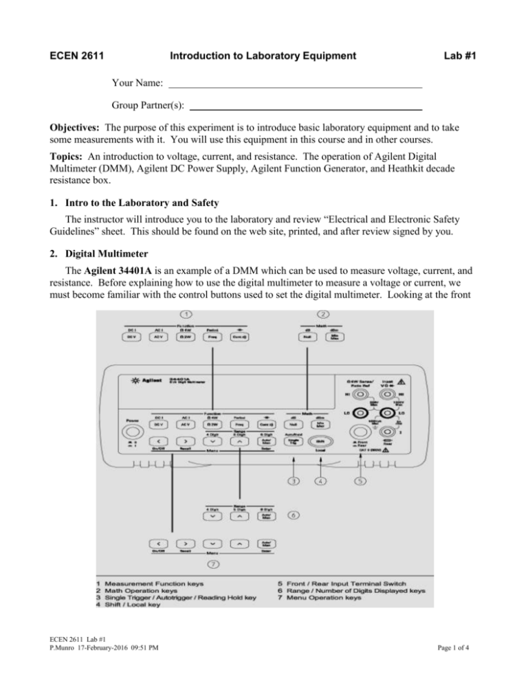
ECEN 2611 Introduction to Laboratory Equipment Lab #1 Your Name: Group Partner(s): Objectives: The purpose of this experiment is to introduce basic laboratory equipment and to take some measurements with it. You will use this equipment in this course and in other courses. Topics: An introduction to voltage, current, and resistance. The operation of Agilent Digital Multimeter (DMM), Agilent DC Power Supply, Agilent Function Generator, and Heathkit decade resistance box. 1. Intro to the Laboratory and Safety The instructor will introduce you to the laboratory and review “Electrical and Electronic Safety Guidelines” sheet. This should be found on the web site, printed, and after review signed by you. 2. Digital Multimeter The Agilent 34401A is an example of a DMM which can be used to measure voltage, current, and resistance. Before explaining how to use the digital multimeter to measure a voltage or current, we must become familiar with the control buttons used to set the digital multimeter. Looking at the front ECEN 2611 Lab #1 P.Munro 17-February-2016 09:51 PM Page 1 of 4 panel of this DMM, we see the following sets of buttons: Measurement Functions (1), Math Operations (2), Trigger (3), Shift (4), Input Terminals (5), Range (6), and Menu Operations (7). The function buttons determine the operation of the digital multimeter, such as voltage, current, resistance, frequency, or continuity measurements. When measuring voltage, the AC V and DC V buttons select the mode of operation. AC V (or I) gives a measurement of periodic V (or I) values, whereas a DC measurement gives a value averaged over time. Using the shift button followed by the AC V or DC V button selects AC I or DC I which measures current. The Ohm, Freq, and Cont buttons are used to measure the resistance, frequency (or period), and continuity, resp. In order to get a precise reading you must select an appropriate range for the multimeter. By using the range/digits buttons the range can be set manually or automatically to change the number of digits of precision. In the sections below, we will discuss how to measure voltage, current, and resistance. a) Voltage Measurements To measure a DC or an AC voltage, set the range accordingly. Next, connect the black (negative) probe to ground and touch the red (positive) probe to a point in the circuit where you want to know the voltage. If you want to measure the voltage difference across a resistor, place the black probe at one end and the red probe on the other end of the resistor. Remember that voltage measurements are always between two points. b) Current Measurements To measure the current in an element or a wire, first select the current mode button and then choose the appropriate range. Next you must open the circuit in order to connect the digital multimeter in series with the element. Remember that current measurements give the flow of charge in an element or wire. c) Resistance Measurements To measure the resistance of an element in a circuit, first remove it from the circuit to ensure a correct (accurate) reading. Next select the appropriate range and mode of operation, and then connect each end of the element to the digital multimeter. 3. Function Generator The Agilent 33220A is an example of a function generator. A function generator is used to provide voltages that vary with time. A function generator provides the following waveforms: sine, square, ramp, pulse, noise, and other arbitrary waveforms. These are parameters that can be varied for each waveform. They include: a. Amplitude b. Frequency c. DC offset ECEN 2611 Lab #1 P.Munro 17-February-2016 09:51 PM Page 2 of 4 4. DC Power Supply When using the Agilent E3631A DC Power Supply start by connecting wire leads to the appropriate voltage range desired. Once the leads from the power supply are correctly connected to a proper load, use the output on/off button to enable the output terminals, and then use the adjust knob to obtain the voltage or current desired. 5. Decade Resistance Box Our decade resistance boxes provide resistances ranging from 0 to 999,999 ohms. The decade box has six knobs. Each knob allows you to select its range from 0 to 9, and from knob to knob the values increase by a factor of ten. Total resistance is the sum of each knob-value times its respective factor. 6. Measurement Exercise Measuring some body resistances Begin by using the DMM to measure the resistance between your thumb and index finger on one hand. You may want your lab partner to hold the probes to your finger and thumb to establish good contact or press the probes between finger/thumb and bench surface. Repeat this for your other hand. Describe how you do this, and record and label your readings. (Note that Descriptions are very important for all your lab reports.) ECEN 2611 Lab #1 P.Munro 17-February-2016 09:51 PM Page 3 of 4 Next measure the resistance between your hands by squeezing the probes tightly between your index finger and thumb of each hand. Compare this value with the resistance between your thumb and index finger. Use the internet or library to justify your results. For next lab, type a short paper explaining your results and including all references such as texts, drawings, etc. Measuring circuit values Build the circuit in Figure 1 using decade boxes. Use the DMM to measure the resistances of and the voltages across resistors R1, R2, R3, R4, R5, and R6. If you need help, please ask your instructor. Then measure the currents in the resistors R1, R2, R3, R4, R5, and R6. Summarize your results in the following table and be sure to include units with each value. And describe what you do! Resistor Resistor setting Measured value Voltage Across Resistor Current in Resistor R1 R2 R3 R4 R5 R6 R3 2k R1 R4 1k R5 3k 5k V1 20Vdc R2 4k R6 2.5k 0 Figure 1. Experimental Circuit Due: End of this lab session. Format: You should write your reports on the unlined side of engineering paper, and please write legibly and as neatly as possible. If you wish, reports may be typed and printed, but be sure to include original data pages. Staple these lab sheets as the cover on the top of your report with the staple put neatly in the upper left corner. ECEN 2611 Lab #1 P.Munro 17-February-2016 09:51 PM Page 4 of 4


