thick settlements
advertisement
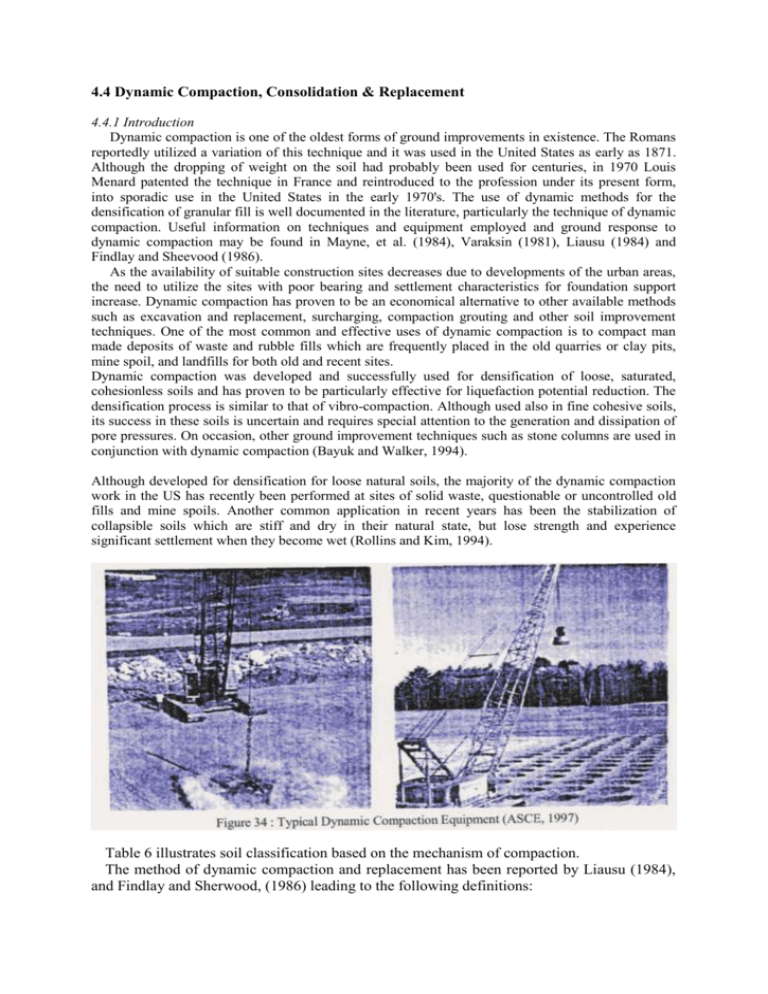
4.4 Dynamic Compaction, Consolidation & Replacement 4.4.1 Introduction Dynamic compaction is one of the oldest forms of ground improvements in existence. The Romans reportedly utilized a variation of this technique and it was used in the United States as early as 1871. Although the dropping of weight on the soil had probably been used for centuries, in 1970 Louis Menard patented the technique in France and reintroduced to the profession under its present form, into sporadic use in the United States in the early 1970's. The use of dynamic methods for the densification of granular fill is well documented in the literature, particularly the technique of dynamic compaction. Useful information on techniques and equipment employed and ground response to dynamic compaction may be found in Mayne, et al. (1984), Varaksin (1981), Liausu (1984) and Findlay and Sheevood (1986). As the availability of suitable construction sites decreases due to developments of the urban areas, the need to utilize the sites with poor bearing and settlement characteristics for foundation support increase. Dynamic compaction has proven to be an economical alternative to other available methods such as excavation and replacement, surcharging, compaction grouting and other soil improvement techniques. One of the most common and effective uses of dynamic compaction is to compact man made deposits of waste and rubble fills which are frequently placed in the old quarries or clay pits, mine spoil, and landfills for both old and recent sites. Dynamic compaction was developed and successfully used for densification of loose, saturated, cohesionless soils and has proven to be particularly effective for liquefaction potential reduction. The densification process is similar to that of vibro-compaction. Although used also in fine cohesive soils, its success in these soils is uncertain and requires special attention to the generation and dissipation of pore pressures. On occasion, other ground improvement techniques such as stone columns are used in conjunction with dynamic compaction (Bayuk and Walker, 1994). Although developed for densification for loose natural soils, the majority of the dynamic compaction work in the US has recently been performed at sites of solid waste, questionable or uncontrolled old fills and mine spoils. Another common application in recent years has been the stabilization of collapsible soils which are stiff and dry in their natural state, but lose strength and experience significant settlement when they become wet (Rollins and Kim, 1994). Table 6 illustrates soil classification based on the mechanism of compaction. The method of dynamic compaction and replacement has been reported by Liausu (1984), and Findlay and Sherwood, (1986) leading to the following definitions: a) Dynamic Compaction: the compaction by heavy tamping of unsaturated or highly permeable saturated granular materials. The response to tamping is immediate. b) Dynamic Consolidation: the improvement by heavy tamping of saturated materials in which the response to tamping is largely time dependent. Excess pore water pressures are established as a result of tamping and dissipate over several hours or days after each tamping pass. c) Dynamic Replacement: the formation by heavy tamping of large pillars of imported granular soil within the body of the soft saturated soil to be improved. The original soil is highly compressed and consolidated between the pillars and the excess pore pressure generated requires several hours to dissipate. The pillars are used both for soil replacement and drainage. Figure 35 illustrates grouping of soils by sieve analysis for dynamic compaction (Lukas, 1992). It is worth noting that the method is suitable for pervious and semi-pervious soils with fine contents less than 20% (Zone I, and Zone II). Zone III is relatively impervious soils such as clays and organic deposits. When these deposits are saturated, excess pore pressures develop quickly but because of the low permeability, long periods of time are required for dissipation, which make dynamic compaction impractical. Dynamic compaction has been successful in zone II deposits, but the construction procedure has to be carefully planned so as to allow excess pore pressures to dissipate between impacts. As a guide to categorize the soil deposits into one of the three categories described above, either field permeability tests or laboratory grain size gradation tests could be undertaken. 4.5 Deep Dynamic Compaction 4.5.1 Basic procedure The American Society of Civil Engineers (ASCE) ten years updates on deep dynamic compaction (ASCE, 1997) provides a review of the state of practice of dynamic compaction and its engineering applications. Dynamic compaction is applied in a systematically controlled pattern of drops on a coordinate grid layout The initial impacts are spaced at a distance dictated by the depth of the compressible layer, depth to groundwater, and grain size distribution. Initial grid spacing generally approximates the thickness of the compressible layer. Typically, 5 to 15 blows per grid point are applied. Often, the proximity of groundwater or excessive crater depth limits the number of blows applied to each grid to avoid getting the tamper stuck, or to allow for pore water pressure dissipation. Standard practice is to curtail energy application when crater depth exceeds one and a half to two times the height of the tamper, or when the groundwater surface rises into the crater. When this occurs, additional passes after ground leveling, or backfilling the crater are required to complete the required number of drops. This first phase of treatment is designed to improve the deeper layers. Incorrect spacing and energy level at this stage could create a dense upper layer making it difficult or impossible to treat loose material below. The initial phase is also called the "high energy phase" because the compaction energy is concentrated on a wider grid. Completion of the high energy phase is usually followed by a low energy phase, called "ironing," to densify the surficial layers in the upper 1.5 m (5 ft). Here, the tamper is only raised from 5 to 6 m (15 to 20 ft), and is dropped on an overlapping grid. After each pass, the imprints are either backfilled with the surrounding materials or with off-site material. In a situation where groundwater is at shallow depth, the craters should be backfilled with imported materials to insure staying above the water table. At least 1.5 m (5 ft) is generally required between the tamping surface and groundwater. In saturated fine-grained soils, the process is complicated by the creation of excess porewater pressures during compaction, a phenomenon which reduces the effectiveness of the subsequent compaction passes unless the pore pressure is adequately dissipated. For clayey soils, dynamic compaction is generally not recommended unless the craters are backfilled with crushed stone and repounded, creating large diameter columns of compacted stone (dynamic replacement). 4.5.2 Type of soil improved The single most determinative factor in the suitability of a soil type to be improved by dynamic compaction is its ability to dissipate the excess pore pressure generated by the DC process, During dynamic compaction, soil particles are displaced into a tighter configuration or a tighter state of packing. If water is present in the soil voids, an instant rise in pore water pressure occurs. It is necessary for this pressure to dissipate before additional densification can occur under repeated high energy drops. If this isn't allowed to happen, then repeated drops from the tamper only cause displacement of the ground, and not densification. As with the increase in applications of dynamic compaction over the last decade, the types of materials treated by dynamic compaction have also increased dramatically. Originally, the predominant soil types considered for dynamic compaction included only granular natural or fill soils. But because of the inherent economic advantages involved with the use of dynamic compaction, a multitude of materials have been improved. They include; Uncontrolled fills: Soil types within old fills can include the entire spectrum of natural soils, manmade debris, byproducts, and any combination of the three. Dynamic compaction works best, however, on dry granular fills, including sand, gravel, ash, brickbats, rock, shot rock, and steel slag. Dynamic compaction in granular fills is similar to a Proctor compaction test, in that there is a physical displacement of particles into a denser configuration. Dynamic compaction produces a low frequency vibration, in the range of four to ten cycles per second, and it is this low frequency excitation along with this input of impact energy that reduces void ratio and increases relative density resulting in improved bearing capacity and enhanced settlement characteristics For deposits below the water table, the vibrations cause an increase in pore pressure, and after a sufficient number of surface impacts, cause a sufficient rise in pore pressure as to induce liquefaction, very similar to the process occurring during earthquakes. Once this occurs, additional energy application is ineffective until the pore pressure dissipates. Additional pounding following pore pressure dissipation produces more low frequency vibrations that reorganize the particles into a denser configuration. Dynamic compaction has been used more recently to improve fine-grained fills as well. These Oils are much more difficult to improve, and require much tighter field control and experience. Clays and silts tend to "heave" after repeated pounding, and if additional pounding continues, can have a detrimental effect on compaction. If heaving occurs, pounding at that point should stop, and the number of passes should be increased with either a reduced drop height or fewer drops per point. A more common technique that has been increasingly employed in the US over the past decade to improve fine-grained sites is dynamic "replacement" technique. This technique consists of producing a crater by conventional heavy tamping, and filling the craters with a "boney" or granular backfill material to create in-situ highly compacted large diameters granular pillars, which is either floating or driven to a firm strata. This boney material can be gravel, shot rock, brick bats, reprocessed concrete, or anything that will lock together under additional heavy tamping. Because of the higher permeability of this backfill, pore wafer pressure from the underlying and adjacent fine-grained soils will dissipate more quickly. This process is repeated until a noticeable decrease in crater formation occurs. This technique essentially results in large diameter columns of compacted stone underlying a site or individual column locations Dynamic compaction is often used in conjunction with other ground improvement techniques. A retail site in New Jersey was constructed over an old fill which was underlain by organic soils is an example. Here, a vibroflot was used to install stone columns at each interior footing location, and then the surface deposits at each of these column locations was dynamically compacted (Bayuk and Walker 1994). There have been several old steel mill sites that have been underlain by steel slag (Troy, NY; Youngstown, OH; Trenton, NJ, St. Louis, East Chicago, IN) Steel slag is generally quite granular, and responds very well to dynamic compaction. Municipal Solid Waste (MSW): Post-construction settlements of sanitary and rubble landfills under embankments are difficult to predict. Without site improvement, settlements can sometimes range from 1.5- 4.6 m (5- 15 ft). The main causes of settlement in landfill deposits are due to: • • • • Mechanical compression due to distortion, reorientation of the materials under self-weight, Biological decomposition of organic wastes, Physio-chemical change such as oxidation, corrosion, and combustion, Ravelling of fines into larger voids Dynamic compaction has been used extensively on MSW to remediate the above causes and for a multitude of reasons. Again, experience is essential in improving MSW, in that grid spacing, weight contact pressure, and number of passes are crucial in achieving the desired results. Highway embankments, roadways, parking lots, and even retail structures have increasingly been constructed on dynamically compacted MSW. In sanitary landfills, settlements are caused either by compression of the voids or decaying of the trash material over time, Dynamic compaction is effective in reducing the void ratio, and therefore reducing the amount of immediate and long-term settlements after construction. It is also effective in reducing the decaying problem, since collapse of voids means less available oxygen for decaying process. Future settlements, however, can still be expected due to a secondary consolidation process, and future decaying of the trash material. A distinction must be made between older landfills and more recent landfills when considering the long-term settlement of the landfill after improvement with dynamic compaction. Organic decomposition has generally already taken place in older landfills, and the land5.1l usually consists of a dark-colored soil matrix containing varying amounts of bottles, metal fragments, wood: and debris. Decomposition generally takes more than 25 to 30 years to occur. For deposits where biological decomposition is complete, dynamic compaction has its greatest benefit. Densification results in higher unit weight and reduction incompressibility under load with little long-term subsidence under load. For recent landfills where organic decomposition is still underway, dynamic compaction increases the unit weight of the soil mass by collapsing voids and decreasing the voids ratio. It will not however, stop the biological decomposition, which may result in a loosening of the soil structure followed by long term settlement. Coal Mine Spoil: Drumheller and Shaffer (1997) discussed 19 coal spoil sites in the US that have been improved by dynamic compaction. Dynamic compaction methodology in coal spoils varies with the consistency of coal spoil. Some spoil are predominately shotrock with minor amount of cohesive material, whereas some spoils have much higher concentration of fines. Contact pressure of tamper, size of weight, and grid spacing are generally considered important factors in coal spoils. Depending upon the nature of the proposed structure, dynamic "replacement" is sometimes used following the DC area pass at column locations to further reduce the risk of intolerable settlement. Collapsible Soils: Rollins and Kim (1994), Drumheller and Shaffer (1996), and Davis (1996) discussed eleven sites in Western States where dynamic compaction was used to improve collapsible soils. Settlement associated with collapsible soils can lead to expensive repairs, either in highway or structure construction. In 1982, FHWA conducted an extensive field test program of various ground improvement techniques to improve collapsible soils in New Mexico. The various techniques included vibroflotation, deep mixing, pre-wetting, and dynamic compaction. Dynamic compaction was found to be the most cost effective, and was selected to improve three separate sections of I-25 and I-40 around Albuquerque. Liquefiable Soils: dynamic compaction is a useful ground improvement tool to reduce liquefaction potential as it increases the relative density as well as lateral earth pressure. Disc et al., (1994) with the US Bureau of Reclamation, discussed three large projects where dynamic compaction was used to remedial liquefiable soils and improve the seismic stability of several embankment dams. 20 to 30 tone tampers were employed at all of these locations. Wick drains and surface drainage were installed in conjunction with the dynamic compactian at the sites. 4.5.3 Dynamic Consolidation For soft cohesive soils, the densification of soil following heavy tamping is attributed to; (a) Compressibility of saturated soil due to the presence of micro-bubbles; (b) The gradual transition to liquefaction under repeated impacts; (c) The rapid dissipation of pore pressures due to high permeability after soil fissuring; (d) Thixotropic recovery. With successive tamping, energy is imparted to the soil, a certain amount of immediate volumetric strain is mobilized, and excess pore pressure is generated. The level of energy input into the system is called the ‘saturation energy’ when the pore pressures equal 100% liquefaction pressure. No further volume change can be achieved by imparting additional energy to the soil. Dissipation of pore pressures with time leads to consolidation and gain in strength of the soil. The process of densification under a number of passes with time delays between each pass can be visualized from Fig. 3. The background of the analysis of the heavy tamping mechanism has been described in detail by Van Impe (1992). For low-velocity impacts on soft cohesive soils the impact energy is used efficiently to improve the soil only in a thin layer. If the impact energy is very high, as in the case of common dynamic consolidation of normally consolidated soils, the depth of influence and the final compacted density are greater, although the energy partly dissipates due to radiated longitudinal stress waves. Beneficial effects such as inhibiting heave and greatly increasing the impact efficiency have been obtained recently in Belgium by the Soils company patented impact block, capable of extending the duration of the pulse on the soil being treated, towards a more ‘plastic collision', and allowing implementation of variable block stiffness by prestressing the anchors (Van Impe, 1992). The extent to which heavy tamping improves the in situ soil is one of the primary parameters studied. 4.5.4 Design and Analysis Considerations: The design of a dynamic compaction project involves determination of tamper weights, grid pattern, drop heights, and depth of influence. The following section briefly discuss theses design parameters (Lukas, 1986; Menard and Boris, 1975; Van Impe et al, 1997; Mayne et al, 1984). Depth of Improvement, D, Prediction of the depth of influence and the level of improvements are the primary concern when using the dynamic compaction method. These, however, depend on several other factors which include: the soil conditions, energy per drop, the contact pressure of the tamper, grid spacing, number of passes and the time lag between each pass. Impact Energy, E, The energy induced by the dropping of the tamper is simply the weight of the tamper times the height of the drop. These represent the main design parameters in determining the depth of improvement when using dynamic compaction. Menard and Broise, (1975) proposed that depth of influence was simply proportional to the square root of the energy per blow, the equations was modified later by Lukas, 1986. D= n (WH)0.5 Where, D = Depth of Influence (meters) W = Weight of Tamper (tonnes) H = Height of Drop ( meters ) n = empirical coefficient that depends on the type of soil (0.3 to 0.6) This equation is based on the free falling of the weights. (1) The factor n, is to account for the applied energy, tamper contact pressure, influence of cable drag, presence of energy absorbing layers and ground water table. Table 7 lists the proposed values of n, for applied energy with the range of 34 to 100 ton.ft/ft2. Figure 37 graphically shows the range for various case histories (Leonard et al, 1980). The grid spacing is related to the impact energy by the following equation, E = (NWHP)/S2 (2) Where, E is the average applied energy over the treated area, N, is the number of drops, P is the number of passes, and S is the grid spacing. Lukas (1986) ves typical impact energy values per unit volume of treated soils. These values can be multiplied by the thickness of the treated soil to estimate the required applied energy at the surface. The estimated energy is used in the above equation to determine either the number of drops for a specific spacing or the minimum spacing for a particular number of drops. The grid spacing usually used is about 1.5 to 2.5 times the dimensions of the tamper (Munfakh, 1997). Influence of Cable Drug, since dynamic compaction is a repetitive process, substantial amount of time is required to manually rehook the weight after each drop. As a result, drops are conducted with the cable attached to the tamper This however poses another problem due to the influence of cable drag which is due to friction of the cable unwinding over the spool drum and reduction in tamper velocity due to air resistance. Lukas (1992) bases his observations on five separate dynamic compaction projects indicating that whenever tampers are reused and dropped with a single cable with a free spool, the measured velocity was found to range from 0.88 to 0.93 of the theoretical velocity. Results were, however, encouraging since the influence of the cable drag on the energy applied was relatively constant and, hence, does not have to be measured for each equipment or tamper weight. Equipment Limitations, The type of equipment used will also have an effect on depth of influence. Conventional crawler cranes with a rated capacity of 136 tons are commonly used for dynamic compaction for drop heights up to 24 meters. The usual mass of tamper used however is in the order of 10 to 20 tons with drop heights usually ranging from 10 to 20 meters. Higher drop energies have been achieved with tamper masses of up to 150 tons and drop heights as high as 40 meters with special cranes or tripods. Influence of Tamper Size, Tamper size is instrumental in controlling the contact pressure at impact. Contact pressure which is defined as the weight of tamper divided by the contact area is commonly used in the range from 30 to 75 kN/m2. Low contact pressure could develop a crust of soil and prohibit any soil improvements below this crust Conversely contact pressure higher than those indicated above could result in the temper punching into the ground upon impact, which reduces energy efficiency. Grid Spacing, The print spacing (the spacing between the compaction points) used in dynamic compaction has a significant effect on the soil improvement within the grid (Chow, et al, 1994). The first pass is designed to improve the deeper level, and is dependent on the thickness of the compressible layer, grain size distribution and depth of the groundwater. Initial grid spacing is usually at least equal to the thickness of the compressible layer. Other passes that follow are aimed at densifying shallower level, which may also require lesser applied energy. Finally, an "ironing" pass to densify the top layer of the ground is conducted by dropping of a square or rectangular tamper over the entire surface area with relatively low drop energy. Time Delay between Passes, Where pore-water pressure can develop, the timing between each pass must be such that it will allow for the pore-water pressure to dissipate Piezometers can be installed to monitor the dissipation of pore-water pressure following each pass Soil Conditions, As described before, dynamic compaction is best suited for densification of deposits grouped as pervious and semi-pervious (Lukas 1986). In addition, the position of the water table and the amounts of fine contents generally influence the effectiveness of dynamic compaction. Presence of clay content greater than I5% fines by weight, generally renders this method less effective (Luongo, 1992) Degree of Improvement, Main factor controlling the degree of improvement is the applied energy. Menard and Broise (1975) stated that the applied energy used for Dynamic Compaction, should produce a minimum static load of 2 - to 3 t/m2 at the depth corresponding to the water table level. Other suggestions were also made for magnitude of the applied energy. Lukas (1992) based his recommendations on different types of soil conditions as shown in Table 7. Although increasing the number of drops in each pass and ice number of passes can be used to achieve a greater depth of influence, there is a point for which the further application of energy produces only minimal gains. This threshold is called the "saturation energy". Lukas, (1992) presented a typical graph of depth of improvement versus the number of drops. Depending on the soil type, increase in the number of drops will have very little gain in improvement of the lower levels. For cohesive soils, Charles et al. (1981) proposed an influence depth which takes into consideration other parameters such as soil type, surface area and shape of the pounder. D = 0.4 (EdB/Apcu)0.5 (3) where B is the width or diameter of the pounder, Ed/Ap is the total impact energy applied per unit area of the pounder and cu is the undrained shear strength of the soil. An exhaustive compilation of data from over l20 sites was presented by Mayne et al. (1984). Moreover, useful correlation for normalized crater depth, D/(WH)0.5, overall subsidence of the ground, peak particle velocity, and maximum depth of influence, D, have been presented. The normalized crater depth increases with the number of passes (Fig. 5a), the trend showing a limit for this parameter. The overall ground subsidence increases with applied energy (Fig. 54), while peak particle velocity decreases (Fig. 5c) with scaled distance, d. The maximum depth of influence is proportional to the energy per blow. Site Preparations, The site to be consolidated must first be prepared to support the weight of the tamping machine (60- 200t). Occasionally 1 to 2 meters of granular materials are applied to the ground surface, particularly in landfills and other soft ground conditions, to provide bearing surface for the machine. It must also be safeguarded against bad weather. If sensitive to rain water (alluvia and clays ), and removal of water rising to the surface during the consolidation process must be facilitated by means of peripheral trenches, drains, and so on. 4.5.5 Environmental Considerations One major concern with heavy tamping is the high impact energy that generates damaging ground vibrations The use of such methods of ground improvement is therefore much more limited in the urban surroundings. Ground vibrations caused by dynamic compaction not oniy can be damaging to the nearby structures, under ground utilities and electrical or mechanical equipment, and are also disturbing to people. Vibrations are normally quantified in terms of the Peak Particle Velocity (PPV). Peak particle generally used to define the damage criteria for buildings and the annoyance tolerance levels to people. Figure 39 shows the relationship between particle velocity is and scaled energy factor. It illustrates that well-constructed buildings can tolerate a PPV of 50 mm/sec, however, a limit of12.5 mm/sec is often used as a maximum value for safety margin. To facilitate comparison between various projects, the peak particle velocity has been plotted against the inverse scaled distance as shown in Figure 39. The inverse scale distance is the square root of compaction energy, (WH)0.5, divided by distance from the impact point. 4.5.6 Other Design Considerations Many dynamic compaction sites have irregular subsurface conditions particularly boulder and rubble deposit where it is difficult to interpret verification test results and assess soil properties after dynamic compaction improvement. Based on extensive laboratory model study of dynamic compaction of dry sand with measurements included tamper acceleration and soil pressure during impact, a procedure was presented by Poran et al (1992) to use Dynamic Settlement Modulus (DSM) to determine the degree of improvement during construction. DSM was defined as the slope of the tangent of the loading portion of impact stress-relative settlement curve where relative settlement, ej, is defined as the tamper settlement dt, divided by its diameter, D. DSM = pt / (dt/D) (4) where, pt, is the impact stress. Also, DSM values is a function of tamper drops, As it can be observed, for most of the tests, the rate of DSM increase was significantly reduced from the 12' drop on This relative change in the DSM values was found to be proportional to the rate of densification (density increase as a function of Number of drops). Although not widely used, other design methods have been developed in order to make a better prediction of the effect of factors affecting dynamic compaction and the required or the desired level of ground improvement Lo, et al (1990) introduced a DC design method based on their findings that a relationship exists between the saturation energy and enforced settlement. The authors presented a plot (Figure 40) of enforced settlement versus total applied energy intensity, pointing out that for a given initial soil consistency and energy per blow of pounder, a hyperbolic curve may reasonably be fitted to the field results Thus, a saturation energy can be defined beyond which further enforcement of settlements would be relatively insignificant. Furthermore, saturation energy intensities were plotted against the ratio of energy per blow of tamper Ey (energy per blow) to the initial pressuremeter limit pressure PL of each site. As shown in Figure 41, a unique relationship may reasonably be constructed between parameters Is (saturation energy) and EB/PL. The authors also emphasized that in view of scarcity of well-documented tamping projects to draw upon, the assumed trends for IS in Fig 8 have been inferred on the basis of rather limited data. Additional research would no doubt refine the results, establishing more reliable design curves. Further, since IS is uniquely determined by EB/PL it should in principle, be reasonable to expect that a collective term of these parameters relating to the operational requirements of each tamping project would similarly determine the maximum degree of ground improvement uniquely. This collective term or operational factor maybe expressed as = IS (EB/PL) (5) where, IS = Saturation Energy (t-m / m‘) EB = Energy per Blow (t-m) PL = Pressure meter Limit Pressure (t/m‘) The maximum degree of ground improvement maybe expressed in terms of enforced settlement per unit thickness of treated soil deposits as follows: = SE/Ht (6) where, Ht = total initial thickness of soil deposits requiring treatment According to Figure 41, the relationship would then be applicable. = /(30+3) (7) Thus, given the initial ground conditions, it may in principle be possible to specify a priori, with the characteristics of Figure 41, energy per below of pounder print spacing, and number of below per print to achieve the required degree of improvement, and thereby rationalize performance design Furthermore, due to the subsequent thixotropic recovery and dissipation of pore-water pressure, long terms effects of heavy tamping might result in greater ground improvement than inferred herein. 4.5. 7 Dynamic Replacement Dynamic replacement is based on the same mechanism of densification as dynamic compaction and utilizes similar plant, essentially a tall rig with a drop weight. It further incorporates ground replacement techniques by progressively filling the crater, or "prints" formed by the drop weight with rock fill to create columns of strong, heavily compacted material. The columns greatly improve the average stiffness of near surface zone, as well as better transmitting the impact forces from the drop weight to greater depths within the fill. The basic processes involved in dynamic replacement are indicated in Figure 42. The main design parameters for this technique could be summarized as (Barksdale and Bachus, 1983), i) shear strength h of the composite mass of vertical compacted granular material within the existing soft soils; ii) stress ratio deemed as loads transferred to columns to that transferred to adjacent soils, which will be a function of the soft material stiffness (cohesion), and the volume of the replaced material per unit volume of the soft soils, iii) vertical capacity of the columns, governed by the diameter and allowable confining pressures provided by the surrounding soils; iv) drainage properties of the replaced soils and their influence on the consolidation and strength gain of the soft soils. The main draw back of dynamic replacement is that the improved soil may experience 40 % of the estimated settlement without improvement due to the fact that soils between columns, while improved through the compaction induced lateral compression are not treated in the same manner. As reported by Bevan, 1997 a major dynamic replacement project for a multi-story building was carried out in Iran for ground improvement to enhance settlement and strength characteristics of soft sandy clayey soils. Boreholes revealed either very silty collapsing sandy soils above ground water or soft compressible sandy clay below ground water table overlying a marl bedrock at a depth between zero to 12 meters below finished facility ground level. Low standard penetration test ($PT) blow counts are observed just above ground table. Ground table varied between about 3 to 4 meters below finished floor level. There appeared generally to be a stiff surface crust across the whole site with loose to very loose horizons just above and below the ground water table. The initial proposal was to improve the alluvial deposits by Dynamic Compaction. However, due to the high content of fines, mainly the clayey fraction, the process becomes dynamic replacement. In this particular site, plugs of stone, consisting of imported backfill, which is repeatedly filled into the craters by the pounder, were driven into the soil. These plugs were reinforcing the existing soil to a certain extent as load supporting elements. They reduced the settlement, increased the bearing capacity and accelerate the consolidation process. To test the effectiveness of the spread treatment from the tamping points, tests were carried out with various number of drops and CPT's made at the center of the print and at 1,2,3,4, and 5 meter Rom the center of the print. Figure 43 illustrates that the effect is concentrated in the layer above the water table and at the center of the tamping print area in the plan. Disruption of the original surface crust between 0 and 2 meter can be observed, which would need careful restoration in ironing pass.


