Wavefront Aberrations
advertisement
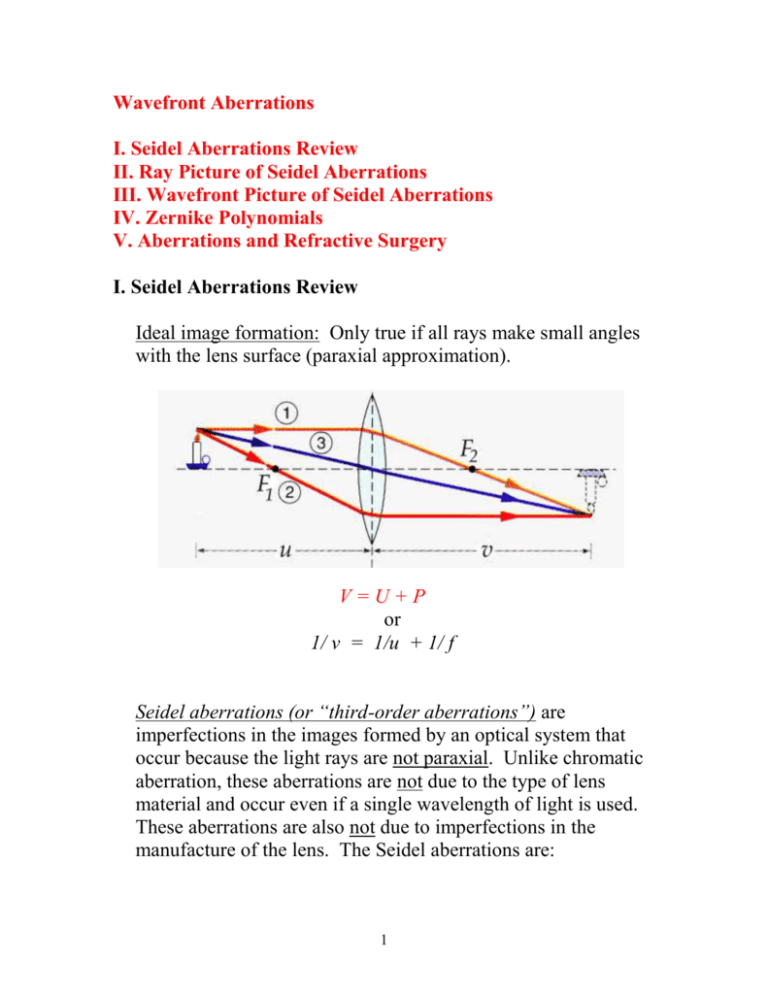
Wavefront Aberrations I. Seidel Aberrations Review II. Ray Picture of Seidel Aberrations III. Wavefront Picture of Seidel Aberrations IV. Zernike Polynomials V. Aberrations and Refractive Surgery I. Seidel Aberrations Review Ideal image formation: Only true if all rays make small angles with the lens surface (paraxial approximation). V=U+P or 1/ v = 1/u + 1/ f Seidel aberrations (or “third-order aberrations”) are imperfections in the images formed by an optical system that occur because the light rays are not paraxial. Unlike chromatic aberration, these aberrations are not due to the type of lens material and occur even if a single wavelength of light is used. These aberrations are also not due to imperfections in the manufacture of the lens. The Seidel aberrations are: 1 1. Spherical aberration 2. Coma 3. Radial astigmatism 4. Curvature of field 5. Distortion 1. Spherical aberration The effect: Paraxial rays and peripheral rays are imaged at different distances from a spherical lens. TSA A B Question #1: Which set of the sets of rays shown are the paraxial rays? Correction: 1. Somewhat costly methods of correction: aspheric lenses, GRadient INdex lenses (GRIN), lens combinations. 2. Use spherical surfaces that minimize LSA. The optimum occurs when the light bends equal amounts at each surface. This, in turn, depends upon the object and image positions. 2 Spherical aberration is minimum for a specific shape of lens that depends on object and image distances. Here S is called the “Coddington Shape Factor” and is a number that describes the shape of the lens. 2. Coma The effect: Off-axis rays spread into a comatic flare at the paraxial image plane, similar to the shape of a comet’s tail (hence the name). Correction: 3 As with spherical aberration, use spherical surfaces that minimize coma. Again, the best choice will depend on the object and image positions. Coma is zero for a lens with S = 0.8 and an object at optical infinity Coma 4 3. Radial astigmatism The effect: off-axis rays in different meridians (planes) are imaged at different distances from the lens. Basically, a spherical lens behaves like a spherocylindrical lens for offaxis rays. Tangential rays Sagittal image Tangential image Sagittal rays For the figure above, the object point is vertically offaxis. The tangential plane is the plane of the paper and the sagittal plane is perpendicular to this plane. The rays diverging from the object point in the tangential plane are imaged as a line perpendicular to the plane of the paper and those diverging in the sagittal plane are imaged as a line parallel to the paper. Correction: As with other aberrations, the shape of the lens can correct for RA. Corrected curve spectacles are designed reduce radial astigmatism. 5 Tscherning ellipses specify the front and back vertex powers for a spherical lens that give zero RA for one off-axis angle. These values of the vertex powers are used in lens design to minimize RA (just as the Coddington shape factors are used to minimize spherical aberration and coma). Tscherning ellipses specify the appropriate front surface power of a lens that corresponds the necessary back vertex Rx to give zero RA 4. Curvature of field The effect: The image plane of a lens is not actually a plane – it is a curved surface. Therefore, different pieces of an extended object are imaged at different distances from the lens. This leads to curved images of straight objects. Paraxial image plane Actual image is curved Correction: An appropriate combination of lenses can be used to eliminate (or at least significantly reduce) curvature of field. 6 5. Distortion The effect: The lateral magnification, m, changes with offaxis angle This distorts the image in the paraxial image plane in one of two ways: a) pincushion (m increases with increasing ) b) barrel (m decreases with increasing ). Correction: combinations of lenses that exhibit barrel and pincushion distortion II. Ray Picture of Seidel Aberrations One approach to understanding the source of the Seidel aberrations is by considering rays of light incident on a lens surface. As described earlier, these aberrations occur because the light rays are not paraxial. Paraxial approximation: assume that all angles between light rays and lens surface are small so that we can use the approximation sin ≈ Lenses and the paraxial approximation: 7 Snell’s Law: n1 sin1 = n2 sin2 Paraxial Snell’s Law: n1 1 ≈ n2 2 The paraxial approximation allows us to find simple relationships between objects and their ideal images (like V = U + P). In reality, many of the rays that are incident on a lens are NOT paraxial. So, ideal images are NOT formed. We can begin to see the effects of this if we expand the sine function in a power series expansion: sin = 3/3! + 5/5! .... In the paraxial approximation, we keep just the first term on the right hand side. Seidel aberrations result from the third-order (3) term. Seidel Snell’s Law: n1( 3/3!) ≈ n2( 3/3!) In fact, an exact analysis of all aberrations can be done by not using any approximations, following a large number of rays through the optical system, and using Snell’s Law in it’s exact form for each ray at each lens surface. The disadvantage is that this can be computationally very difficult and take a great deal of computing power. In order to avoid having to do this and still get many of the important features of the aberrations, we make approximations about the shape of the aberrated wavefront that leaves the optical system. III. Wavefront Picture of Seidel Aberrations 8 In order to form an ideal (aberration free) image, the wavefronts that form the image of a point object must be spherical. Real object point Real image point Spherical wavefronts If there are aberrations present in an optical system, the wavefronts that form the image are no longer spherical. Goal: Quantify the ways in which the wavefronts are not spherical in order to design the optical system to alter the wavefronts so that they are as close to spherical as possible (minimize aberrations). exit pupil of optical system ideal wavefront y paraxial image plane R x ideal image point 9 Mathematically, we can describe the shape of the ideal wavefront as: x2 y2 W(x,y) 2R This is just the paraxial equation for a sphere of radius R centered at the paraxial image point. It is often convenient to use cylindrical coordinates instead so we use x = cos() and y = sin() so that we can express the wavefront as 2 W(x,y) 2R If the optical system suffers from aberrations, the wavefront will not be perfectly spherical anymore. We to account for the case that the paraxial image also need location might not be on axis (off-axis object location). exit pupil of optical system ideal wavefront y paraxial image plane R x h aberrated wavefront 10 ideal image point centered a distance h off axis Mathematically, we try and express the aberrated wavefront as the sum of the ideal wavefront plus some correction terms that account for how far the real wavefront is from ideal. If the aberrations are all Seidel aberrations the wavefront can be expressed as: 1 1 1 1 1 W(x, y) Wideal S1 4 S 2 h 3 cos() S 3 h 2 2 cos2 () (S 3 S 4 )h 2 2 S 5 h 3 cos() 8 2 2 4 2 spherical aberration coma astigmatism curvature of field Here S1-S5 are constants that depend on the characteristics of the optical system. If any of them are zero, that particular aberration does not exist for that optical system. Some things to notice: 1) Spherical aberration is the only “on axis” aberration (no dependence on h) 2) All of the Seidel aberrations can be reduced by limiting and h (paraxial approximation) 3) If astigmatism is present (S3 not zero) than curvature of field will also be present 4) Coma, astigmatism, and distortion are not symmetric about the optic axis (depend on ) Question: Which Seidel aberration will likely have the biggest effect on a patient’s vision? A. spherical aberration B. coma C. astigmatism D. distortion 11 distortion Practice with Seidel Wavefronts An instructive visualization tool can be found at: http://wyant.optics.arizona.edu/seidelWavefrontMaps/s eidel.htm Begin by setting all of the coefficients equal to zero. Turn on the focus term to see how it produces an ideal wavefront. Next turn on each Seidel aberration one at a time to see how it affects the ideal wavefront. IV. Zernike Polynomials The Seidel aberrations do not describe all possible aberrations of the wavefront! Goal: Find a way to quantify the discrepancy between an arbitrary aberrated wavefront and the ideal spherical wavefront. Idea: Find a set of mathematical functions that can be added together in various combinations to form any arbitrary waveform at the exit pupil of an optical system. * Look at analogous situation We can get an understanding of how this works by considering a different (and simpler) situation: making 1-dimensional waveforms using sines and cosines (Fourier Analysis). It turns out that we can make any arbitrary repeating waveform by adding together appropriate amplitude 12 and frequency sine and cosine waves (Fourier’s Theorem). In mathematical terms this means that we can write: 2n 2n f(x) a n cos x b n sin x where f(x) is the waveform we are trying to produce, an and bn are constants that depend on the waveform we are trying to produce, and is the fundamental wavelength of the waveform. Practice with Fourier Analysis Go to the Physics Education Technology website: http://phet.colorado.edu Click on “Play with sims” “Math” “Fourier: Making Waves”. This is a java based program and has trouble opening sometimes so you may need to close it and open it again. Be patient. Begin by playing the “Wave Game” for the first few game levels (1-4) to begin to get some experience for how sine waves can be added together to make a more complicated waveform. Next, go to “Discrete” and look at how sine waves of the appropriate amplitudes can be added to produce a triangle wave and a square wave. 13 Of particular imporatance for later discussions: Which waveform (triangle or square) can be best represented by adding together a small number of sine waves? * End of analogy We want to find a set of mathematical functions (like the sines and cosines are for 1-D waveforms) that can be added together over a 2-D circular aperture (the exit pupil) to produce any arbitrary waveform. It turns out that the appropriate functions for this situation are the “Zernike Polynomials”. The first nine are listed below (there are an infinite number of them). Zo = 1 Z1 = cos() Z2 = sin() Z3 = 22 – 1 Z4 = 2cos2(2) Z5 = 2sin2(2) Z6 = (32 – 2)cos() Z7 = (32 – 2)sin() Z8 = 64 - 62 + 1 So, an arbitrary waveform at the exit pupil of an optical system can be written as: W(,) Wn Z n where Wn are constants that depend on the shape of the waveform we are trying to represent (like the a’s and b’s in the Fourier Analysis case). 14 Note: When analyzing waveforms using Zernike polynomials the reference case is typically a plane wave leaving the exit pupil (flat wavefront). The first 4 Zernike polynomials (Z0-Z3) correspond to an ideal spherical wavefront centered on the paraxial image point and are NOT aberrations: Z0 is a constant or “piston” term that changes the overall phase of the wave but does not affect the image Z1 and Z2 are “tilt” or “prism” terms that shift the center of the spherical wavefront to the correct paraxial image location Z3 is a “focus” term that gives the correct curvature to the spherical wavefront to cause the paraxial image Practice with Zernike Polynomials An instructive visualization tool can be found at: http://wyant.optics.arizona.edu/zernikes/zernikes.htm Begin by setting all of the coefficients equal to zero. Turn each of the first 4 on one at a time (set the coefficients to some small non-zero number) to see how these produce an ideal wavefront. Zernike Polynomials and Seidel Aberrations Suppose we write out the full wavefront expansion for an arbitrary aberrated wavefront using the first 9 Zernike polynomials. We obtain: 15 W(,) W0 W1 cos() W2 sin() W3 (2 2 1) W4 2 cos(2) W5 2 sin(2) W6 (3 2 2) cos() W7 (3 2 2) sin() W8 (6 4 6 2 1) Take a moment to compare this expression with that for the Seidel aberrated wavefront that we wrote down earlier. Some important things to note: a. There are many terms that look pretty similar (as they should since we are hoping to be able to express any aberrated wavefront using appropriate Zernike polynomials). b. The Zernike wavefront has no h dependence! That is clearly a problem since we know the actual Seidel aberrations do depend on the off-axis distance. That turns out to be ok because we can determine the off-axis dependence by doing a Zernike expansion of the wavefront corresponding to each off-axis image location. c. The first 4 terms (along with contributions from some higher order terms) determine the paraxial (ideal) wavefront. If we do a little math and ignore some angular shifts (for the sake of clarity of this discussion) the relationships are approximately: Focus 2W3 6W8 W42 W52 Tilt (W1 2W6 )2 (W2 2W7 )2 Additionally, the Seidel coefficients (S) can be related to the Zernike coefficients (W). Again, ignoring some angular shifts the relationships are approximately: 16 S1 = 48W8 (spherical aberration) S 2 6 W62 W72 (coma) S 3 4 W42 W52 (astigmatism) Note: Because the Zernike wavefront expansion does not give us any off axis height (h) dependence for a single image location the Seidel aberrations of Curvature of field and Distortion look like additional tilt and focus (same and dependence if you compare those Seidel and Zernike terms). More Practice with Zernike Polynomials Go back to the website that allows us to visualize the Zernike abberated wavefronts. Try turning on appropriate Zernike coefficients to make a wavefront that could be described by spherical aberration, coma, and astigmatism (be careful – remember that the focus and tilt terms might be altered!) Of course, that is not the whole story! The Zernike expansion can describe many more aberrations than the Seidel aberrations can! Try turning on some of the higherorder aberration coefficients and see what they do to the wavefront. V. Abberations and Refractive Surgery The ultimate goal of refractive surgery would be to completely eliminate refractive error including all wavefront aberrations by resculpting the cornea to have the correct shape. The first steps toward this are being taken through “custom wavefront” refractive surgery. 17 How might this be accomplished? Idea: Measure the aberrated wavefront that exits the eye when a small region of the retina is illuminated (acts as a point source). By the principle of reversibility if we can send a wavefront into the eye that has this same aberrated shape it will form a perfect point image on the retina (except for diffraction). So the goal becomes to take a plane wave (from an object at optical infinity) and intentionally aberrate it so that it has the correct shape for the eye to form an ideal image on the retina. How do we measure the aberrated wavefront? There are several techniques. But the most popular is probably: Shack-Hartmann Wavefront Sensor http://www.lzr.com/centers/seattle/what_history.fxml If the wavefront entering the lenslet array is a perfect plane wave, each lens in the array will form a point image at its focal point on the sensor. This is the reference situation. 18 If the wavefront entering the lenslet array is aberrated, the point image formed by each lens will be shifted on the sensor by an amount proportional to the slope of the wavefront at that lens. This information from all the lenses can be combined to give the shape of the wavefront entering the lenslet array. J. Schwiegerling, “LASIK and Beyond,” Optics and Photonics News, January 2002. The aberrated wave is essentially used as a template to etch the cornea with the same shape! 19 Issues to consider (as of 2004): 1. Do higher order aberrations really impact vision? Yes and no. In situations where the pupil size is large (~ 5-6mm) or for highly misshaped corneas (such as keratoconus) the correction of higher order aberrtions can provide significant visual benefit. Also, some studies show that normal LASIK surgery tends to increase the amount of higher order aberrations (particularly spherical) compared to pre-surgery. 2. Does the benefit of wavefront correction apply to all viewing conditions? No! Remember that the correction was done for distance vision (object at optical infinity). If the eye accommodates to view a nearby object, the overall aberrations of the eye change! Why? The refractive power of the eye comes from both the cornea and the crystalline lens and both of these contribute to the overall aberrations of the eye. As the crystalline lens changes power in accommodation, the aberrations it produces change and so do the overall aberrations of the eye. So, the cornea that has been altered to correct for aberrations at distance viewing will not typically give aberration correction for near viewing (and may actually make the aberrations worse for this case). 3. Is the Zernike representation of higher order aberrations the best method for wavefront correction? 20 Unclear. Remember the lesson of trying to make a square wave using sines and cosines! Not all waveforms are practical to make with a small number of sines and cosines. Similarly, not all wavefront shapes are practical to make with a small number of Zernike polynomials! Current practice is to correct a 3.4mm pupil size up to 4th order Zernike aberrations (mostly Seidel) and up to 8th order for a 7.3mm pupil size. However, some studies show that this is not sufficient for all cases and that up to 36 or more Zernike terms may be needed to describe the aberrated wavefront in some instances. That may make the Zernike expansion of the aberrated wavefront impractical in some cases. References R.R. Krueger, R.A. Applegate, and S.M. MacRae, Wavefront Customized Visual Correction: The Quest for Super Vision II, SLACK Inc. (2004). J.C. Wyant and K. Creath, Applied Optics and Optical Engineering, Vol. XI, Chapter 1, “Basic Wavefront Aberration Theory for Optical Metrology,” Academic Press (1992). L.A. Carvalho, “Accuracy of Zernike Polynomials in Characterizing Optical Aberrations and the Corneal Surface of the Eye,” Investigative Ophthalmology & Visual Science, Vol. 46, No. 6 (2005). 21 M.K. Smolek and S.D. Klyce, “Zernike Polynomial Fitting Fails to Represent All Visually Significant Corneal Aberrations,” Investigative Ophthalmology & Visual Science, Vol. 44, No. 11 (2003). S.D. Klyce, M.D. Karon, and M.K. Smolek, “Advantages and Disadvantages of the Zernike Expansion for Representing Wave Aberration of the Normal and Aberrated Eye,” Journal of Refractive Surgery, Vol. 20 (2004). J. Schwiegerling, “LASIK and Beyond,” Optics and Photonics News, January 2002. 22
