ODZ_Optical design with Zemax Exercise 1
advertisement

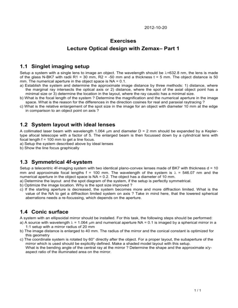
2012-10-20 Exercises Lecture Optical design with Zemax– Part 1 1.1 Singlet imaging setup Setup a system with a single lens to image an object. The wavelength should be =632.8 nm, the lens is made of the glass N-BK7 with radii R1 = 30 mm, R2 = -50 mm and a thickness t = 5 mm. The object distance is 50 mm. The numerical aperture in the object space is NA = 0.1. a) Establish the system and determine the approximate image distance by three methods: 1) distance, where the marginal ray intersects the optical axis or 2) distance, where the spot of the axial object point has a minimal size or 3) determine the location in the layout, where the ray caustic has a minimal size. b) What is the focal length of the system ? Determine the magnification and the numerical aperture in the image space. What is the reason for the differences in the direction cosines for real and paraxial raytracing ? c) What is the relative enlargement of the spot size in the image for an object with diameter 10 mm at the edge in comparison to an object point on axis ? 1.2 System layout with ideal lenses A collimated laser beam with wavelength 1.064 m and diameter D = 2 mm should be expanded by a Keplertype afocal telescope with a factor of 5. The enlarged beam is then focussed down by a cylindrical lens with focal length f = 100 mm to get a line focus. a) Setup the system described above by ideal lenses b) Show the line focus graphically 1.3 Symmetrical 4f-system Setup a telecentric 4f-imaging system with two identical plano-convex lenses made of BK7 with thickness d = 10 mm and approximate focal lengths f = 100 mm. The wavelength of the system is = 546.07 nm and the numerical aperture in the object space is NA = 0.2. The object has a diameter of 10 mm. a) Determine the layout and the spot diagram of the system, if the setup is perfectly symmetrical. b) Optimize the image location. Why is the spot size improved ? c) If the starting aperture is decreased, the system becomes more and more diffraction limited. What is the value of the NA to get a diffraction limited system on axis ? Take in mind here, that the lowered spherical aberrations needs a re-focussing, which depends on the aperture. 1.4 Conic surface A system with an ellipsoidal mirror should be installed. For this task, the following steps should be performed: a) A source with wavelength = 1.064 m and numerical aperture NA = 0.1 is imaged by a spherical mirror in a 1:1 setup with a mirror radius of 20 mm b) The image distance is enlarged to 40 mm. The radius of the mirror and the conical constant is optimized for this geometry c) The coordinate system is rotated by 60° directly after the object. For a proper layout, the subaperture of the mirror which is used should be explicitly defined. Make a shaded model layout with this setup. What is the bending angle of the central ray at the mirror ? Determine the shape and the approximate x/yaspect ratio of the illuminated area on the mirror. 1/1


