wkideal
advertisement

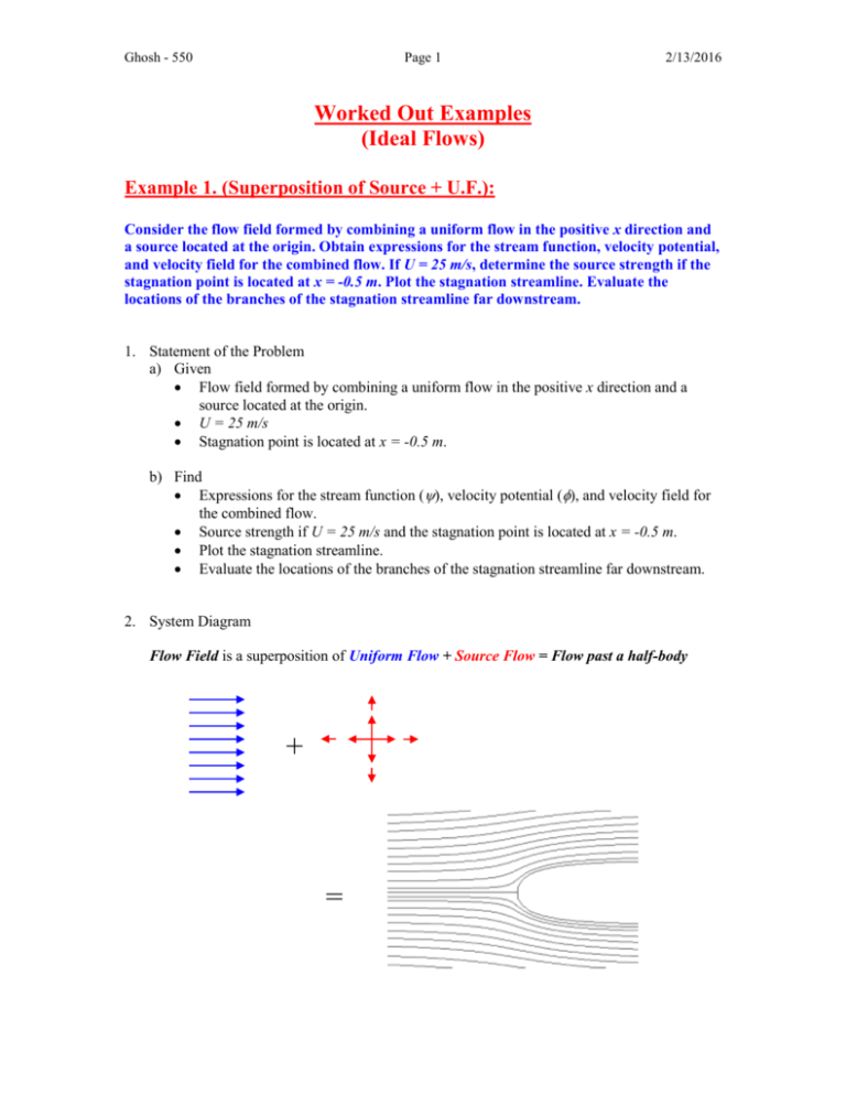
Ghosh - 550 Page 1 2/13/2016 Worked Out Examples (Ideal Flows) Example 1. (Superposition of Source + U.F.): Consider the flow field formed by combining a uniform flow in the positive x direction and a source located at the origin. Obtain expressions for the stream function, velocity potential, and velocity field for the combined flow. If U = 25 m/s, determine the source strength if the stagnation point is located at x = -0.5 m. Plot the stagnation streamline. Evaluate the locations of the branches of the stagnation streamline far downstream. 1. Statement of the Problem a) Given Flow field formed by combining a uniform flow in the positive x direction and a source located at the origin. U = 25 m/s Stagnation point is located at x = -0.5 m. b) Find Expressions for the stream function (), velocity potential (), and velocity field for the combined flow. Source strength if U = 25 m/s and the stagnation point is located at x = -0.5 m. Plot the stagnation streamline. Evaluate the locations of the branches of the stagnation streamline far downstream. 2. System Diagram Flow Field is a superposition of Uniform Flow + Source Flow = Flow past a half-body + = Ghosh - 550 Page 2 2/13/2016 3. Assumptions Steady state condition Incompressible fluid flow Inviscid fluid flow 2 - D problem 4. Governing Equations Stream Function Definition 1 r V r Vr Velocity Potential Definition (2 - D case) r 1 V r Vr Elementary Plane Flows Uniform Flow (positive x direction) Ur sin( ) Ur cos( ) Source Flow (from origin) q 2 q ln( r ) 2 5. Detailed Solution (Note: Stream function, Velocity Potential, Velocity field are all required) Since this is an elementary plane flow problem, the stream function and the velocity potential of the flow field can be obtained by superposition technique: Flow field = Uniform flow + Source flow Stream Function Ur sin( ) q 2 Velocity Potential Ghosh - 550 Page 3 2/13/2016 q q ln( r ) Ur cos( ) ln( r ) 2 2 Ur cos( ) Velocity field can be obtained using either stream function definition or velocity potential definition. Here, use velocity potential definition: Vr q q 1 Ur cos ln r U cos r r 2 2 r V 1 1 r r q 1 Ur cos 2 ln r r Ur sin 0 U sin q 1 er U sin e V Vr er V e U cos 2 r Source Strength Stagnation point is located at x = -0.5 m Vr = V = 0 at r = 0.5 m & = . q 1 q 1 q U cos U 0 2 r 2 0.5 V U sin U sin 0 Vr U cos U q 0 q U q 25 m2/s Stagnation streamline Now, the stream function can be written as Ur sin( ) q U Ur sin U r sin 2 2 2 and the stream function value ss at the stagnation point is ss U r sin U 0.5sin U 2 2 2 Stagnation streamline is U r sin ss U 2 2 U r sin U r sin r sin r 2 2 2 2 2 sin 2 2 Ghosh - 550 Page 4 2/13/2016 Using MatLab, the stagnation streamline plot looks like: Stagnation Streamline 2 1.5 1 y 0.5 Stagnation streamline Origin & Source location Stagnation point 0 -0.5 -1 -1.5 -2 -2 0 2 4 6 x 8 10 12 14 Locations of the branches of the stagnation streamline far downstream Stagnation streamline equation was (See above) r sin 2 r sin (in polar coordinate system) is equivalent to y (in rectangular coordinate system). Thus, y 2 Branches of the stagnation streamline far downstream occur when 0 & 2 . y lim 0 2 2 y lim 2 2 2 Therefore, the locations of the branches of the stagnation streamline far downstream is at Ghosh - 550 Page 5 y 2/13/2016 2 . 6. Critical Assessment Since this is a superposition of an elementary plane flow problem, it doesn't include viscosity. It gives an exact solution to a real case problem as long as the viscous effects are small. In other words, if we are only interested in the ideal pressure flow field, this should be the approach. But viscosity must be included to obtain a more realistic solution, which will be discussed in later chapters. Example 2. (Force Calculation in Ideal Flows): The flow over a Quonset hut may be approximated by the velocity distribution, R 2 R 2 V U 1 cos er U 1 sin e with 0 . During a storm the r r wind speed reaches 100 km/hr; the outside temperature is 5 C. A barometer inside the hut reads 720 mm of mercury; pressure p is also 720 mmHg. The hut has a diameter of 6 m and a length of 18 m. Determine the net force tending to lift the hut off its foundation. U Quonset hut p Tout R pin 1. Statement of the Problem a) Given Velocity distribution: R 2 R 2 V U 1 cos er U 1 sin e for 0 r r U = 100 km/hr = 27.778 m/s Tout = 5 C air = 1.27 kg/m3 p = pin = 720 mmHg = 95.992 kPa D=6mR=3m L = 18 m b) Find Net force tending to lift the hut off its foundation, FL. Ghosh - 550 Page 6 2/13/2016 2. System Diagram p U p pin R Tout pin 3. Assumptions Steady state condition Incompressible fluid flow Inviscid fluid flow Irrotational flow Actually, this can be checked by the rotation z 1 1 rV 1 Vr 0 2 r r r 4. Governing Equations Bernoulli's Equation: p V2 gz const. 2 Restrictions: (1) Steady flow (2) Incompressible flow (3) Frictionless flow (4) Flow along a streamline 5. Detailed Solution Velocity components are: R 2 Vr U 1 cos r R 2 V U 1 sin r R 2 R 2 from the velocity distribution V U 1 cos er U 1 sin e . r r Note that Vr 0 along r = R, so this represents flow around the hut. Flow is irrotational, so the Bernoulli equation may be applied between any two points. Applying the equation between a point far upstream and a point on the surface of the hut (neglecting elevation differences), we obtain p Thus U2 p V2 gz1 gz 2 2 2 Ghosh - 550 Page 7 p p 2/13/2016 1 U 2 V 2 2 Along the surface of the hut, r = R, and R 2 Vr U 1 cos 0 R R 2 V U 1 sin 2U sin R V 2 Vr2 V2 0 2 2U sin 4U 2 sin 2 2 Substituting this expression into the Bernoulli equation, p p 1 1 U 2 4U 2 sin 2 U 2 1 4 sin 2 … 2 2 Lift is the force component normal to the free stream flow direction. (By convention, positive lift is an upward force.) The infinitesimal lift is given by (See the system diagram) dFL pin p sin dA … where dA R d L . Substituting into , 1 dFL pin U 2 1 4 sin 2 p sin dA 2 1 dFL U 2 1 4 sin 2 sin dA since p = pin. 2 1 dFL U 2 1 4 sin 2 sin R d L 2 Finally, integrate this expression over 0 to obtain the lift: Ghosh - 550 Page 8 2/13/2016 1 FL dFL U 2 RL 1 4 sin 2 sin d 0 0 2 1 U 2 RL sin d 4 sin 3 d 0 0 2 cos 3 1 2 U RL cos 0 4 cos 2 3 0 After substituting values, FL = 88.196 kN. 6. Critical Assessment This problem illustrates the use of integration to compute lift in a cylindrical system. Make sure you understand the choice of area element and the lift formulation. It shows that lift (as well as drag) may be non-zero in an ideal flow if the flow symmetry is lost. Continue


