477
advertisement
477 Project Guidelines
Your assignment is to develop an architectural model for the HazMat Rover system
based on the requirements documents you received and which were discussed in class
last week. To guide work on the architectural model, please refer to the abridged
MBASE guidelines. Specifically you should at least consider the following design
issues in your project:
#
DESIGN ISSUE
MBASE SSAD SEC.#
1.
System behavior
OCD 3.3.3, OCD 4.3,
SSAD 2.3
2.
Hardware Component Classifier Model
SSAD 3.1.2
3.
Software Component Classifier Model
SSAD 3.1.3
4.
Deployment Model
SSAD 3.1.4
5.
Architecture Analysis Classes
SSAD 3.2
System behavior
Describe the context of how the system is used. For example, for the HazMat
project, the operator should be able to load the map.
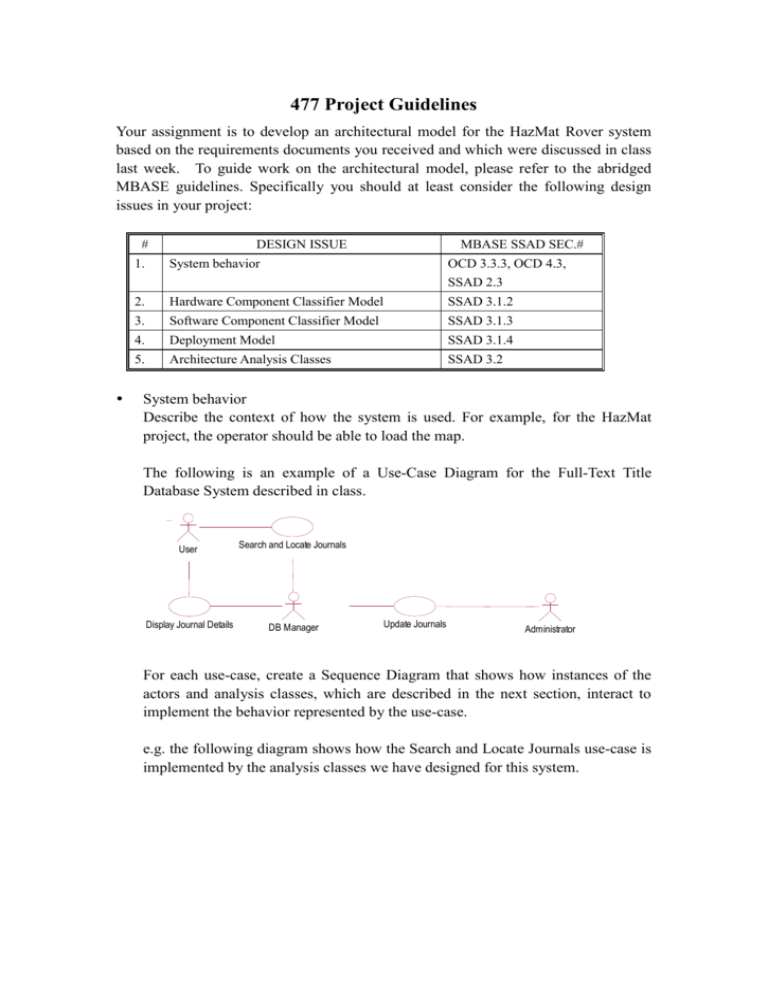
The following is an example of a Use-Case Diagram for the Full-Text Title
Database System described in class.
User
Search and Locate Journals
Display Journal Details
DB Manager
Update Journals
Administrator
For each use-case, create a Sequence Diagram that shows how instances of the
actors and analysis classes, which are described in the next section, interact to
implement the behavior represented by the use-case.
e.g. the following diagram shows how the Search and Locate Journals use-case is
implemented by the analysis classes we have designed for this system.
: User_Agent
: User
: Search_Form
Request_Search( )
User requests search
System displays search page
: Search_Request
JournalManager :
Journal_Set_Manager
Journals : Journal_Set
: Journal_Set
form := Create( )
if result
is empty,
: Results_Form
form contains error
message.
{new}
Display(form)
Modify( )
User enters search criteria
Submit_Search( )
request := Get_Request( )
request := Create(...)
{new}
System queries database
asking for journals that match
user's search criteria
result := Search(request)
result_set := Create( )
{new}
*[for all Journals]
journal := Next()
[journal satisfies criteria] Add(journal)
form := Create(result)
{new}
journal := Next( )
*[while another journal in result]
format(journal)
System displays journal list in
search results page or Displays
error page that asks the user to
search again
Display(form)
Hardware Component Classifier Model
The Hardware Component Classifier Model describes the kinds of hardware
components that are either part of the system or on which this system will run,
and the kinds of connectors that will be used to connect them.
E.g.
<<connector>>
<<node>>
Workstation
+client
Network
0..*
+server
<<node>>
Unix Server
1
Software Component Classifier Model
The Software Component Classifier Model describes the kinds of software
components that are part of the system, the actors for the system with which the
system interacts, and the kinds of connectors that will be used to connect them.
You are expected to present the overall SW component classifier model.
E.g.
Main
Web Server
Browser
(from System Layer)
...)
(from System Layer)
...)
<<Component>>
<<Component>>
Library_User
Web
(from Application Layer)
(from Frameworks)
System_Administrator
(from Application Layer)
java
(from Frameworks)
UserServic
es
MySQL
(from Server
...) Component)
<<Component>>
Server
(from Business Layer)
Administrat
orServices
(from Server
...) Component)
For each component, you should describe the analysis classes that are part of the
component and classes that used by the component which are defined in other
components. These diagrams are part of the Analysis Class Model described below.
e.g.
<<entity>>
Search_Request
User_Agent
(from Server Component)
<<signal>> + Request_Search()
<<signal>> + Submit_Search()
<<control>>
Journal_Set_Manager
(from Server Component)
<<boundary>>
<<boundary>>
Search_Form
Results_Form
<<signal>> + Modify()
+ Get_Request() : Search_Request
+ Create()
0..1
+ Create(results : Search_Result)
+ format(journal : Journal_Description)
<<entity>>
represents>
Journal_Set
1
(from Server Component)
...)
<<boundary>>
<<entity>>
Form
Journal_Description
(from Server Component)
...)
Deployment Model
Deployment Model describes component and connector configuration(s) that
make a working version of the system. (There may be more than one
configurations, e.g. for different modes.) For each configuration, describe the
instances of hardware and software component classes that participate in the
configuration, the allocation of software components to the hardware components,
the instances of hardware connector classes that link the hardware components,
and the instances software connector classes that link the software components.
/Administrator : Workstation
<<Component>>
: System_Administrator
client
local : Network
server
ISD Server : Unix Server
Local / User Station : Workstation
local : Network
client
server
<<Component>>
: Library_User
Remote / User Station : Workstation
Internet : Netw...
client
server
<<Component>>
: Server
<<Component>>
: Library_User
Architecture Analysis Classes
Create a model of the information classes that are needed to support the
architectural structure (SSAD 3.1) and implement the system behavior (SSAD
3.3). The model should include classes representing:
artifacts and information required by the system;
forms defined in the current prototype;
information needed for communication components in the architectural
structure;
control behavior specific to one or a few processes performed by
architectural units (i.e. “recipes” that define how to do something).
<acts for
User_Agent
(from Library_User Component)
...)
User
<<entity>>
<<boundary>>
Search_Request
Results_Form
(from Server Component)
...)
(from Library_User Component)
...)
0..1
1..*
represents>
^represents
1
<<entity>>
Journal_Set
1
collects
(from Server Component)
...)
<<boundary>>
<<entity>>
0..*
Journal_Description
(from Server Component)
...)
Search_Form
(from Library_User Component)
...)
<<boundary>>
Form
(from Library_User Component)
Administrator_Agent
acts for>
(from System_Adminstrator Component)
Administrator
Please note that, in this process, you may find that the requirements document is
ambiguous, inconsistent, and/or incomplete. In order to remedy that, you will need
to consult your customers (contact you TA, who will forward any questions that he
cannot answer to Mr. Brown and other members of the USC-CSE SCRover team).
You will need to document any changes and/or clarifications to the requirements in
your architectural model document. For example, if a component A was added based
on your discussions with the TA, that will need to be made clear.
Recall that MBASE relies on UML as a modeling notation. You may use a UML
editor of your choice. Rational Rose and MS Visio are readily available in ISD labs.
