A friend of mine had a pair of 15” Tannoy Monitors, one in an
advertisement
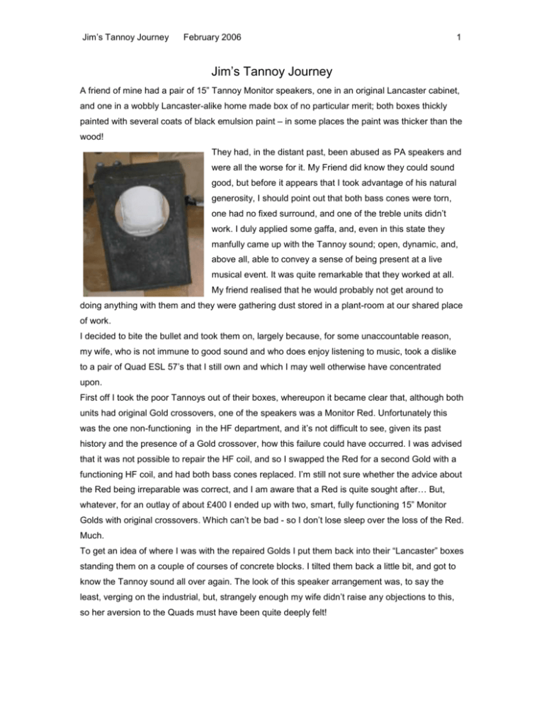
Jim’s Tannoy Journey February 2006 1 Jim’s Tannoy Journey A friend of mine had a pair of 15” Tannoy Monitor speakers, one in an original Lancaster cabinet, and one in a wobbly Lancaster-alike home made box of no particular merit; both boxes thickly painted with several coats of black emulsion paint – in some places the paint was thicker than the wood! They had, in the distant past, been abused as PA speakers and were all the worse for it. My Friend did know they could sound good, but before it appears that I took advantage of his natural generosity, I should point out that both bass cones were torn, one had no fixed surround, and one of the treble units didn’t work. I duly applied some gaffa, and, even in this state they manfully came up with the Tannoy sound; open, dynamic, and, above all, able to convey a sense of being present at a live musical event. It was quite remarkable that they worked at all. My friend realised that he would probably not get around to doing anything with them and they were gathering dust stored in a plant-room at our shared place of work. I decided to bite the bullet and took them on, largely because, for some unaccountable reason, my wife, who is not immune to good sound and who does enjoy listening to music, took a dislike to a pair of Quad ESL 57’s that I still own and which I may well otherwise have concentrated upon. First off I took the poor Tannoys out of their boxes, whereupon it became clear that, although both units had original Gold crossovers, one of the speakers was a Monitor Red. Unfortunately this was the one non-functioning in the HF department, and it’s not difficult to see, given its past history and the presence of a Gold crossover, how this failure could have occurred. I was advised that it was not possible to repair the HF coil, and so I swapped the Red for a second Gold with a functioning HF coil, and had both bass cones replaced. I’m still not sure whether the advice about the Red being irreparable was correct, and I am aware that a Red is quite sought after… But, whatever, for an outlay of about £400 I ended up with two, smart, fully functioning 15” Monitor Golds with original crossovers. Which can’t be bad - so I don’t lose sleep over the loss of the Red. Much. To get an idea of where I was with the repaired Golds I put them back into their “Lancaster” boxes standing them on a couple of courses of concrete blocks. I tilted them back a little bit, and got to know the Tannoy sound all over again. The look of this speaker arrangement was, to say the least, verging on the industrial, but, strangely enough my wife didn’t raise any objections to this, so her aversion to the Quads must have been quite deeply felt! Jim’s Tannoy Journey February 2006 2 Several months, possibly a couple of years, passed. In the meantime I absorbed much about further options from the net, and am grateful to the Tannoy community for their help and advice. I did consider the GRF treatment, but then, like many I guess, was to some extent put off by the complexity of the woodwork. Also, although we had plans for an extension at the time and even though I wasn’t above designing the room to fit the speakers, I wasn’t convinced that I would be able to site the GRF’s in an optimum position, i.e. in corners with those corners allowing anyone listening to sit in a sensible position in the room. I did consider rectangular GRF’s, but felt that if I was going to do the GRF thing I’d rather do it properly than spend all that effort on what might still be regarded as a compromise. From several quarters I heard about a basic ported reflex cabinet, weighing in with a volume of 300 litres. I think Peter Campbell, known to many of us through the Tannoy Group, wrote his most informative piece about just such a design, and several old-school and knowledgeable companies in the UK who are familiar with Tannoys (Lockwood Audio/Wilmslow Audio) independently supported “spending” my Golds in this way. Freedom from any constraints apart from those of the internal volume and the number and size of the ports, was also quite an attractive proposition as I liked the idea of being able to create an original form. Some of the designs I had seen on the net which clearly followed the same basic design seemed to me to be rather tall and to be a bit dominating. Now, I know that any pair of 300 litre boxes are likely to dominate any room South of Buckingham Palace, but I chose to make mine look like smaller speakers in respect of their own proportions, but just to make them a bit bigger! In order to avoid them being tall and wide mine have ended up quite deep. I’m pleased with the look of them and think they fit in well. Needless to say the room doesn’t actually look as tidy as this now… And there is a rug on the floor that looks nice (read: to limit reflections). Jim’s Tannoy Journey February 2006 3 Onwards! Having spent quite a long time digesting all the information I could about a successful design I decided to bear in mind all the following points: Internal volume to be 300 litres. Design to use four ports of 200mm long 4” diameter tube (note carefree attitude towards use of metric and imperial units. I don’t care – I’m not at university any more!!) Design to incorporate a slight tilt back, this to allow the centre of the Golds to be aiming at the head-height of the listener without the cabinets having to be too tall. I also thought that a slight tilt might alleviate any tendency for the HF to bounce up with some directional and possibly phase discrepancy from our hard wooden floor. I also thought that if there was some “beaming” of the HF from the Golds, it might be beneficial for the sound to hit the wall behind the listener at something other than a right-angle, thus not encouraging any particular frequencies to resonate across the room if there was some tendency for them otherwise to do so. Cabinets to be built of all-beech ply. I had heard that this was the best material. Cabinets to be built with much attention paid to limiting the resonance of the cabinet itself. Design to attempt to address issues of reverberation and reflection of pressure waves within the cabinets. Internal bracing to create as much rigidity as I could devise as such a big structure would inevitably comprise large panels. Thickness of walls of cabinet to be… excessive! Structure to avoid internal symmetry where possible in order to lessen any tendency for the air within the cabinets to find frequencies that might resonate. Hard-wiring to be preferable where possible. Keep the crossovers outside the main cabinet. I’ve just realised that I’ve lost all my drawings which I was going to scan in and include… But measuring the speakers from the outside I’ve worked out that the internal dimensions are approx. W 487mm, D 670mm, H 966mm. This multiplies up to more than 300 litres, but I did calculate the displacement of all the bracing and baffles I used. I spent some time with a calculator endeavouring to avoid any one of the three nominal internal dimensions being divisible by, or fractions of, any or both of the other two. Someone with more mathematical prowess than I will undoubtedly tell me that I have got this wrong, but I did try! This was in order to avoid as much as possible any resonances building up as a consequence of certain frequencies finding it easy to hang around in any combination of the three main dimensions inside the cabinets. (The figures above are only approximate as I didn’t spend long just now measuring the cabinets.) Jim’s Tannoy Journey February 2006 4 I designed a cabinet of two skins; an internal one of 18mm all-birch ply, which would then be clad in a 25mm all-birch ply outer layer. I cut scale-panels out of paper and, by placing them over same-scale pieces of paper representing 8’ x 4’ sheets of ply, devised an economical cutting list. I think I ended up with 4 sheets of 25mm ply and 5 of 18mm ply; more 18mm because I was going to use this for the internal structures and to build boxes for my crossovers. I used a jigsaw for the less critical internal cabinet, but cut all the 25mm panels with a hand saw for greater accuracy. Not all at once, I can assure you! The cost of the ply (2004) was about £800. Not cheap, I know, but I had decided to do this once and only once, and if I had used some other cheaper alternative I may have always had the “what if…?” thought reverberating in my head. I decided to use three horizontal bracing panels, deliberately placed at different and irregular distances from the top and bottom panels and from each other in order to reduce the risk of internal resonances building up against the faces of the bracing panels. The Build I was helped by both sons in the work – particularly Sam who spent hours with me working through how we were going to approach different aspects of the build. I’m quite well aware that a professional woodworker would have breezed through this, but, whilst handy, I was nervous about making mistakes and probably thought through each cut unnecessarily slowly. Sam, although only 13 at the time, showed quite a flair for being able to visualise the work. It was a good thing for us to do and to show him the importance of boring measurement and accurate cutting. I bought a router and was going to use it for all the circular cut-outs, but found it blunted quickly and didn’t cut in the same place after several plunges at each site. My fault, I expect, but then 25mm + 18mm of all-birch ply is quite a challenge. In the end I jigged all the cut-outs and only used the router to round off selected edges. To mount the Golds themselves I jigged out a smaller hole in the 18mm internal box to which the speaker was to be bolted from the outside, and a larger one in the 25mm front panel into which the entire speaker fitted. In this way the Gold was front-mounted and therefore no substantial access to the insides of the cabinet would be necessary. In addition I could, of course, remove the speaker unit at any time. Similarly, I jigged a smaller hole in the 25mm front panel to match the inner diameter of the reflex tubes, and a larger one to take the outside diameter of the tubes in the 118mm ply. In this way the tubes were securely butted up against the rear side of the front panel. Obviously I had to deduct the 25mm thickness of the front panel from the overall 200mm of the tube length, and the tubes were cut to a length of 175mm. I had been made aware that it might be advantageous to avoid the cabinet walls all being the same thickness, and maybe thus not allow resonances to build up within the ply itself. To avoid this I cut random holes (where I didn’t need fixing points) out of the 18mm thick panels that made up the internal boxes. These were irregular in size and positioning in order to avoid symmetry. Jim’s Tannoy Journey February 2006 5 Another advantage of this two-box build was that I could be unfussy about showing screws and holes and all sorts of ills. Then, with the size of the box allowing me ready access to the spaces inside the build, I had room to fix the outer 25mm panels onto the 18mm box by screwing out from the inside. This left no screws showing from the outside nor any screw holes to be filled apart from, in the end, the rear panel as this, unless I took up permanent residence, had to be screwed from the outside. This was all very satisfactory and worked well. I cut the outer panels along the outside of my pencil lines, leaving enough timber to be able to plane and then sand the edges as required to get a pretty good fit for all panels. A bit of experience that may be useful to the uninitiated; to a fault I “measured twice and cut once.” By being absolutely rigorous with the thought that if I wasn’t sure I should stop, step back and measure again, I saved the work several times… This picture shows some of the random holes in the internal box and how I built up the 18mm ply box onto the 25mm thick front panel. I had already drilled and secured the captive nuts to take the bolts from the front when securing the driver. I had also cut out areas of the bracing panels. It may by now have become clear that I was a bit of a mission to do all I could think of to minimise any factors that could detract from the sound that the Golds could produce. A further measure I took was to draw out a scale diagram showing how the pressure waves generated behind the LF cone might be stopped from reflecting off the rear panel of the cabinets to the back of the cone again. If this was allowed to happen it would, obviously, affect how purely the LF cone was responding to the incoming signal. A way of stopping this happening might be to pack the cabinets with absorbent fibres until reflections were satisfactorily minimised, but I didn’t want to use too much wadding as, I thought, this might detract from the lovely open and dynamic sound that the Golds can produce. So I devised an asymmetrical “double-V” pair of deflectors behind the cones, and the somewhat excessive depth of the cabinets helped here in that I could use angles of enough shallowness to allow reflections off my baffles to keep moving backwards as they Jim’s Tannoy Journey February 2006 6 bounced along, losing energy all the time. Ultimately they were allowed to reflect off the rear panel of the cabinets, but then only to be steered into a pair of vee-shaped “traps” into which I’d packed just a tiny bit of the absorbent wool I had used from the one original Lancaster cabinet. Internal reflections off the top panel would also be affected by the double-vee in the same way. Any pressure waves inclined to travel down through the cabinet, through holes cut through the bracing panels, would encounter a bit more wadding and have general difficulty in returning to muck about with the rear of the cone. A sketch (definitely not to scale) but still showing the principle of my “Double-Vee” design. To scale I drew the possible pattern of rear radiation and worked out the angles the “Vee” arrangements had to be to stop pressure waves returning to the back of the cone. This is not an arrangement I arrived at through anything other than instinct, so it may be flawed! From the front looking in this is the pointy end of the Vee arrangement. There are no 25mm side panels fixed at this stage, but that does allow a bit of light in which helps the photo. The idea is that the rear of the speaker doesn’t see a flat surface from which radiating sound can reflect back onto the rear of the cone. The vee baffles are angled in such a way that all “waves” always travel away from the cone, then bounce off the flat back panel into traps rather than forwards again onto the rear of the driver. Jim’s Tannoy Journey February 2006 7 This is a photo of the speaker, more or less finished, from the back. The internal angles of the Vee are where the intention is to capture the progressively weaker reflections. I suppose I was thinking of the B&W “Nautilus” arrangement here. The rear of the cone is clearly inaccessible from the rear of the cabinet although the overall volume as seen by the driver is not greatly reduced. The 25mm thick outer panels are fixed at this stage, and the reflex tubes are safely knocked home. Thinking about it I don’t think I ever glued these in! They were a really tight fit, and, in any case, I can still put my hand in from the front and drag them forward and glue them if they ever felt inclined to move. The heights at which the bracing panels are placed was also calculated so that no other internal dimension was replicated in the build. The volume of all the internal woodwork was calculated to leave the overall volume at 300 litres. I finished all the woodwork bar the final sanding and polishing, and screwed on the back panel. I stuck my head in the speaker-hole and hummed my way up and down scales so that I could hear whether particular frequencies produced excessive resonance, which of course they did, so, whilst this was a good talking point for any casual visitors (fewer by the day) I don’t think I proved anything much about the design. Jim’s Tannoy Journey February 2006 8 I had been advised about the amount of wadding to buy, and had duly stuffed it in to the cabinets until it was all gone. In this condition, incidentally, humming my sweep-tones produced almost no This is the amount of ringing at any particular frequencies. wadding I ended up not I used the 4-pin original Tannoy plug and leads using. This is from both connected appropriately to a 4-way connection speakers, but it’s still a lot! panel, housing the crossovers outside the main cabinet in a separate box. I thought that this would not only avoid possibly deleterious physical disturbance to the crossover, but would also allow easy access to the crossovers if I ever wanted to work on them. I soldered the various necessary ins and outs from my crossover box, and the time had come to plug and play! It all worked, I’m pleased to say, but there wasn’t much dynamism to the sound, and it was, to be honest, a bit of a disappointment. However, out came almost all the stuffing – really, there’s now very little in there at all, and there it was; plenty of nice clean bass and the Tannoy dynamics I was expecting. Wadding is definitely best deployed in small quantities. Interestingly there’s now so little wadding in the cabinets that my self-generated sweep tones would be booming away at different frequencies if I stuck my head in again for a quick hum, but a CD-generated sweep (from a Hi-Fi News and Record Review test disc) doesn’t excite the boxes in this way at all – the apparent amplitude sweeping up from 20Hz at listening distance alters very little in the bass. From the same disc I have established that the response is even from about 35 Hz up, and audible from around 20Hz. though I’ve no way of actually measuring this accurately. Once into the midrange and treble there are small peaks and troughs when listening to the sweep tone as it marches onwards and upwards, but at these frequencies I’m guessing that one is a slave to the Jim’s Tannoy Journey February 2006 9 treble horn and not really dealing with cabinet issues. Also, in the real world of listening to music I’m not aware of any particular pitch being inappropriately loud or quiet as different frequencies are re-played. At this stage in the proceedings I took the Golds out again and sanded and polished the cabinets; plenty of work there because the cabinets are quite big. I finished them with no-colour wax; actually “BriWax” if this is of any interest to others. The all birch ply does look quite nice, incidentally, all polished up. Then I cleaned up the sitting room (by allowing me to turn our brand new extension into a workshop - how much do you think my wife hates the Quads?) and went about siting the new cabinets in the room. I had intended to point them along the length of the 12m x 7m room, but ended up putting them either side of the chimney breast across the room. This worked for the living space as well as for the sound; now I could look forward to sitting in front of a lovely fire whiling away hours listening to the Tannoys! And I did. For a bit. Phase 2 Someone made the terrible mistake of lending me a pair of crossovers of their own design… Well, the mistake was more mine, I suppose, for borrowing them. Little did I know when I plugged them in the additional journey I was embarking on, and I don’t suppose I’m finished yet… These borrowed crossovers, recently identified by Peter Campbell (to whom I owe a debt of gratitude for e-helping me through some of my more ignorant moments), as a derivative of those designed for a Tannoy Red, had obvious failings – a rather thin sound and a serious tendency to produce a piercing mid-range emphasis that flashed in my eardrums – but also gave the Golds an indefinable listenability. I found myself listening to the music not the sound, and understanding the words of songs. The imaging was fantastic; absolutely pin-point - much better than that achieved through my original crossovers. These crossovers worked, it appeared, by providing quite a direct signal path, (on the HF side there was no coil/autotransformer and no “energy” choices), and then, by allowing one to choose from a range of resistors in the roll-off area, one could try and find the point where the treble energy was balanced with the roll off of that treble. The Borrowed Crossover. There was no notch filter. Jim’s Tannoy Journey February 2006 10 The borrowed crossover. I hope you forgive my poor grasp of symbols! It was a flawed design, as I said, but, up to a point, it worked. As Peter said, I think that all the time one was fiddling with the sound of the top end by selecting different values of resistance on offer (I settled on 18 ohms), I was altering the crossover point as well, and this might have led to the thinning of the sound and the greater presence of informative mid-range at the expense of a bit of body. This might explain the clear words and the good imaging. I work in the field of live sound, and I found that with this crossover it was possible to really hear into an event, and even be aware, say, of how a piano had been mic’d. This was such a seductive sound, albeit flawed, that I decided I ought to look at what was going on in my crossovers. I took my original crossovers apart and replaced all the capacitors with re-badged Solens, the wire-wound resistors with new ones (I think the original resistors had suffered a bit during their PA days) and cut out the switches; hardwiring onto chosen points of the crossover circuit. I removed the 4-pin plug and socket arrangement on the chassis itself and hard-wired back to the crossover, replacing all wire with Kimber 4TC which is also my speaker cable. Unfortunately I got something so wrong that I caused myself (and Peter) weeks of grief. Instead of putting back the 30 ohms of resistance in the “roll-off” section of the circuit, I soldered 18ohm and 12 ohm resistors in parallel and not in series. This gave me such problems, and I fiddled about with different resistors in inappropriate places in order to compensate for the sound not being quite right in all sorts of unlikely ways. In my ignorance I was altering the crossover point whilst listening for top-end roll-off; using different values of resistors in place of the 30 ohms; removing the notch filter and often inadvertently changing some unknown electrical element of Jim’s Tannoy Journey February 2006 11 the crossover whilst trying to alter an aspect of the sound by listening to something else. I tried all the different taps out of the autotransformer and then trying all the other resistor options again… It was quite a frustrating time. Then I suddenly saw the light, and realised that the 30 ohm had never been replaced properly… I put the 30 ohms back in series and tried both the yellow and green taps on the autotransformer, finally settling on the green (direct) tap. The sound suddenly gelled, and the eq. is very accurate; instruments and voices sound very natural. I am still aware, however, that even though the overall tonal information is accurate, the ultimate directional and dynamic information still lags behind these particular facets of the sound that I enjoyed with the borrowed crossovers. To try and achieve the best of both worlds I tried inserting different values of resistance in front of the notch filter, the intention being to allow an amount of the mid-range through that was totally unattenuated in the borrowed crossovers and which, I thought, might have led to this sometimes improved sense of “presence,” albeit at the cost of accuracy. I have settled on 1.1 ohms in this position, and intend to put a small switch on the notch filter that enables me to run with either the untouched original notch filter in circuit, or with a 1.1 ohm resistor in series with the notch filter if a recording just needs a bit of help with definition and happens not to get too excited and squawky as it strays from accuracy of tone. However, after all the fiddling about, I find that I more or less always listen without the 1.1 ohm resistor switched into the circuit. The original circuit, (albeit with new capacitors), via the green tap, has proven to be the best! Who was I to ever doubt it? One further tweak suggests itself, and that is that perhaps I should remove the dust cap over the tweeter? I wonder if this might add the final element of directional and dynamic leading-edge information whilst not altering the tonal accuracy for the worse, but it is a drastic and irreversible step, and I’m not sure I’m ready for that. And this is where I am now. I wonder if this is the end of my journey? Final Thoughts In conclusion; this whole Tannoy business is as frustrating or as enjoyable as one wants it to be. By any normal standards the sound I now enjoy is streets ahead of anything I have heard “off the peg” in other peoples’ systems. However I am equally certain that many Tannoy enthusiasts would feel I still had a long way to go. The crossover components I have settled on, the use of a passive crossover at all, the amp I use and the sources themselves are all open to question. I have joined a Tannoy group on Yahoo! and it is clear that many in the Tannoy World have gone much further than I am inclined to go, or am, indeed, capable of going. It can also get really expensive yet still remain a matter of trial and error. I am now in the position of thoroughly enjoying recordings that suit the system I have, and during such listening moments feel that there is no need to try and improve on any aspect of the sound. I have, incidentally, also noticed how critical is the volume of replay. Unsurprisingly most jazz recordings are wonderful, folk music and classical work also tend to sound good. Jazz, folk, classical, “modern classical” are where I’m at, Jim’s Tannoy Journey February 2006 12 so really that’s it, isn’t it? There are, however, too many poor recordings/transfers of music that I should like but which sound so awful that I just can’t sit through them. I am also aware that on some days I think everything’s great, and on others the same track(s) can sound a bit wearing or dull or whatever… This is, I suggest, just normal and maybe we all find that our perceptions change from day to day. I guess what I’m saying is that if music can be just fine on a system then maybe that’s as good as a system needs to, or, even can be – isn’t it? ******************* I am aware that my amp and, now, speakers are probably under-nourished in terms of source quality. However, I just don’t have thousands of pounds to spend on more exotic components. I would be interested to hear of any modestly priced new or second-hand source components that informed readers could point me towards. Sources; Denon DL 110 High Output MC cartridge / Linn Basik LV X arm / Garrard 301 on Martin Bastin plinth. CD: Arcam Alpha 5. Also have higher spec. Sony MiniDisc recorder. Amp; Audio Noto Soro “Signature” integrated. Speakers: well… Where do I start?
