Tutorial_Sheet_8
advertisement
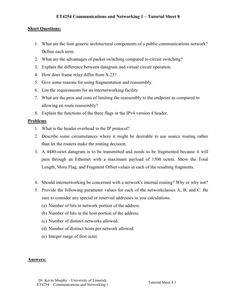
ET4254 Communications and Networking 1 – Tutorial Sheet 8 Short Questions: 1. What are the four generic architectural components of a public communications network? Define each term. 2. What are the advantages of packet switching compared to circuit switching? 3. Explain the difference between datagram and virtual circuit operation. 4. How does frame relay differ from X.25? 5. Give some reasons for using fragmentation and reassembly. 6. List the requirements for an internetworking facility. 7. What are the pros and cons of limiting the reassembly to the endpoint as compared to allowing en route reassembly? 8. Explain the functions of the three flags in the IPv4 version 4 header. Problems 1. What is the header overhead in the IP protocol? 2. Describe some circumstances where it might be desirable to use source routing rather than let the routers make the routing decision. 3. A 4480-octet datagram is to be transmitted and needs to be fragmented because it will pass through an Ethernet with a maximum payload of 1500 octets. Show the Total Length, More Flag, and Fragment Offset values in each of the resulting fragments. 4. Should internetworking be concerned with a network's internal routing? Why or why not? 5. Provide the following parameter values for each of the networkclasses A, B, and C. Be sure to consider any special or reserved addresses in you calculations. (a) Number of bits in network portion of the address. (b) Number of bits in the host portion of the address. (c) Number of distinct networks allowed. (d) Number of distinct hosts per network allowed. (e) Integer range of first octet. Answers: Dr. Kevin Murphy – University of Limerick ET4254 – Communications and Networking 1 Tutorial Sheet 8.1 ET4254 Communications and Networking 1 – Tutorial Sheet 8 1. Subscribers: the devices that attach to the network, such as telephones and modems. Subscriber line: the link between the subscriber and the network. Exchanges: the switching centers in the network. Trunks: the branches between exchanges. Trunks carry multiple voice-frequency circuits using either FDM or synchronous TDM. 2. (1) Line efficiency is greater, because a single node-to-node link can be dynamically shared by many packets over time. (2) A packet-switching network can perform data-rate conversion. Two stations of different data rates can exchange packets because each connects to its node at its proper data rate. (3) When traffic becomes heavy on a circuit-switching network, some calls are blocked; that is, the network refuses to accept additional connection requests until the load on the network decreases. On a packet-switching network, packets are still accepted, but delivery delay increases. (4) Priorities can be used. Thus, if a node has a number of packets queued for transmission, it can transmit the higher priority packets first. These packets will therefore experience less delay than lower-priority packets. 3. In the datagram approach, each packet is treated independently, with no reference to packets that have gone before. In the virtual circuit approach, a preplanned route is established before any packets are sent. Once the route is established, all the packets between a pair of communicating parties follow this same route through the network. 4. Frame relay is much simplified, compared to X.25. The major differences are that frame relay uses out-of-channel signaling while X.25 uses all in-channel control. In frame relay there is no "hop-by-hop" flow control or error control as there is in X.25. If a frame error is detected it is just dropped rather than being retransmitted. Similarly, on an end-to-end basis, there is no error control or flow control except what is provided by higher level protocols outside of frame relay. Finally, frame relay is a two level (physical and link) layer protocol and the multiplexing of logical channels takes place at Level 2 rather than in the Level 3 Packet Layer as in X.25. Dr. Kevin Murphy – University of Limerick ET4254 – Communications and Networking 1 Tutorial Sheet 8.2 ET4254 Communications and Networking 1 – Tutorial Sheet 8 5. (1) The communications network may only accept blocks of data up to a certain size. (2) Error control may be more efficient with a smaller PDU size. With smaller PDUs, fewer bits need to be retransmitted when a PDU suffers an error. (3) More equitable access to shared transmission facilities, with shorter delay, can be provided. (4) A smaller PDU size may mean that receiving entities can allocate smaller buffers. (5) An entity may require that data transfer comes to some sort of "closure" from time to time, for checkpoint and restart/recovery operations. 6. (1) Provide a link between networks. At minimum, a physical and link control connection is needed. (2) Provide for the routing and delivery of data between processes on different networks. (3) Provide an accounting service that keeps track of the use of the various networks and routers and maintains status information. (4) Provide the services just listed in such a way as not to require modifications to the networking architecture of any of the constituent networks. This means that the internetworking facility must accommodate a number of differences among networks. 7. If intermediate reassembly is not allowed, the datagram must eventually be fragmented to the smallest allowable size along the route. Once the datagram has passed through the network that imposes the smallest-size restriction, the fragments may be unnecessarily small for later networks, degrading performance. On the other hand, intermediate reassembly requires compute and buffer resources at the intermediate routers. Furthermore, all fragments of a given original datagram would have to pass through the same intermediate node for reassembly, which would prohibit dynamic routing. Dr. Kevin Murphy – University of Limerick ET4254 – Communications and Networking 1 Tutorial Sheet 8.3 ET4254 Communications and Networking 1 – Tutorial Sheet 8 8. The More bit is used for fragmentation and reassembly. If this bit is 0, then either there has been no fragmentation of this packet or this is the last fragment. If this bit is 1, then this packet has been fragmented and this is not the last fragment. The Don't Fragment bit prohibits fragmentation when set. Problems 1. The header is a minimum of 20 octets. 2. Possible reasons for strict source routing: (1) to test some characteristics of a particular path, such as transit delay or whether or not the path even exists; (2) the source wishes to avoid certain unprotected networks for security reasons; (3) the source does not trust that the routers are routing properly. Possible reasons for loose source routing: (1) Allows the source to control some aspects of the route, similar to choosing a longdistance carrier in the telephone network; (2) it may be that not all of the routers recognize all addresses and that for a particular remote destination, the datagram needs to be routed through a "smart" router. 3. The original datagram includes a 20-octet header and a data field of 4460 octets. The Ethernet frame can take a payload of 1500 octets, so each frame can carry an IP datagram with a 20-octet header and 1480 data octets. Note the 1480 is divisible by 8, so we can use the maximum size frame for each fragment except the last. To fit 4460 data octets into frames that carry 1480 data octets we need: 3 datagrams × 1480 octets = 4440 octets, plus 1 datagram that carries 20 data octets (plus 20 IP header octets) The relevant fields in each IP fragment: Total Length = 1500 Total Length = 1500 Total Length = 1500 Total Length = 40 More Flag = 1 More Flag = 1 More Flag = 1 More Flag = 0 Offset = 0 Offset = 185 Offset = 370 Offset = 555 Dr. Kevin Murphy – University of Limerick ET4254 – Communications and Networking 1 Tutorial Sheet 8.4 ET4254 Communications and Networking 1 – Tutorial Sheet 8 4. No. That would violate the "separation of layers" concept. There is no need for IP to know how data is routed within a network. For the next hop, IP specifies another system on the same network and hands that address down to the network-layer protocol which then initiates the network-layer routing function. 5. Class A: (a) 8 bits, (b) 24 bits, (c) first bit of the first octet in a class A address is 0 (leaving 7 bits), so 27 = 128 – 2 (0 and 127 are disallowed) = 126 networks, (d) 224 = 16,777,216 – 2 (host address cannot be all 0’s or all 1’s) = 16,777,214 hosts, (e) range: 1 through 126 Class B: (a) 16 bits, (b) 16 bits, (c) first two bits of the first octet in a class B address are 10 (leaving 14 bits), so 214 = 16,384 networks, (d) 216 = 65,536 – 2 (host address cannot be all 0’s or all 1’s) = 65,534 hosts, (e) range: 128 through 191 Class C: (a) 24 bits, (b) 8 bits, (c) first three bits in the first octet in a class C address are 110 (leaving 21 bits), so 221 = 2,097,152 networks, (d) 28 = 256 – 2 (host address cannot be all 0’s or all 1’s) = 254 hosts, (e) range: 192 through 223 Dr. Kevin Murphy – University of Limerick ET4254 – Communications and Networking 1 Tutorial Sheet 8.5
