Gai-posipol-06
advertisement
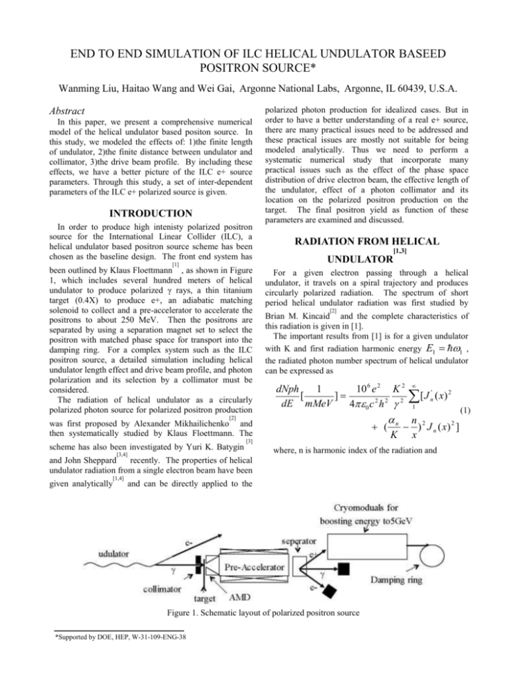
END TO END SIMULATION OF ILC HELICAL UNDULATOR BASEED POSITRON SOURCE* Wanming Liu, Haitao Wang and Wei Gai, Argonne National Labs, Argonne, IL 60439, U.S.A. Abstract In this paper, we present a comprehensive numerical model of the helical undulator based positon source. In this study, we modeled the effects of: 1)the finite length of undulator, 2)the finite distance between undulator and collimator, 3)the drive beam profile. By including these effects, we have a better picture of the ILC e+ source parameters. Through this study, a set of inter-dependent parameters of the ILC e+ polarized source is given. INTRODUCTION In order to produce high intenisty polarized positron source for the International Linear Collider (ILC), a helical undulator based positron source scheme has been chosen as the baseline design. The front end system has [1] been outlined by Klaus Floettmann , as shown in Figure 1, which includes several hundred meters of helical undulator to produce polarized γ rays, a thin titanium target (0.4X) to produce e+, an adiabatic matching solenoid to collect and a pre-accelerator to accelerate the positrons to about 250 MeV. Then the positrons are separated by using a separation magnet set to select the positron with matched phase space for transport into the damping ring. For a complex system such as the ILC positron source, a detailed simulation including helical undulator length effect and drive beam profile, and photon polarization and its selection by a collimator must be considered. The radiation of helical undulator as a circularly polarized photon source for polarized positron production polarized photon production for idealized cases. But in order to have a better understanding of a real e+ source, there are many practical issues need to be addressed and these practical issues are mostly not suitable for being modeled analytically. Thus we need to perform a systematic numerical study that incorporate many practical issues such as the effect of the phase space distribution of drive electron beam, the effective length of the undulator, effect of a photon collimator and its location on the polarized positron production on the target. The final positron yield as function of these parameters are examined and discussed. RADIATION FROM HELICAL [1,3] UNDULATOR For a given electron passing through a helical undulator, it travels on a spiral trajectory and produces circularly polarized radiation. The spectrum of short period helical undulator radiation was first studied by [2] Brian M. Kincaid and the complete characteristics of this radiation is given in [1]. The important results from [1] is for a given undulator with K and first radiation harmonic energy E1 1 , the radiated photon number spectrum of helical undulator can be expressed as dNph 1 10 6 e 2 K 2 [ ] dE mMeV 40 c 2 h 2 2 [3] [1,4] and can be directly applied to the Figure 1. Schematic layout of polarized positron source *Supported by DOE, HEP, W-31-109-ENG-38 ( x) 2 1 where, n is harmonic index of the radiation and and John Sheppard recently. The properties of helical undulator radiation from a single electron beam have been given analytically ' n n ( ) 2 J n ( x) 2 ] K x was first proposed by Alexander Mikhailichenko and then systematically studied by Klaus Floettmann. The [3,4] [ J n [2] scheme has also been investigated by Yuri K. Batygin (1) 1 (1 K 2 ) 1 K 2 ] 0 x 2K 1 (1 K 2 ) detailed process on calculating the polarization of produced positrons is complicated and described in details n2 [n [1] (2) J n : Bessel functions From this spectrum, we can obtain the harmonic distribution function and photon energy distribution function which will be discussed in next section. For the field amplitude of radiation, it can be obtained as [1] Ix ( E ) n 1 10 6 e 2 K n n [ ] 40 2 c 2 K x J n ( x) ( 2 2 n ) 2 Iy ( E ) i n 1 (3) 10 6 e 2 K 40 2 c 2 J n ' ( x) ( 2 2 n2 ) One important feature of the above equation is for a given radiation photon frequency, the radiation from different harmonics have different radiation angle as 1 (1 K 2 ) n [n 1 K 2 ]1 / 2 1 (4) therefore, the radiation field from different harmonics can not be added up and then be treated as one kind of photon, even it may have the same energy. We rewrite equation (3) in terms of harmonic and energy as Ix ( E , n) 10 6 e 2 K n n [ ]J n ( x) 40 2 c 2 K x I I 2 x 2 y , 2 0 , 3 2I x I y I x2 I y2 (6) rotated by 45 with respect to the original one for 3 describes the circular polarization. PHOTON SPECTRUM FROM A DISTRIBUTED ELECTRON DRIVE BEAM AND FINITE LENGTH UNDULATOR For a system layout in Figure 1, one has to consider effects of a distributed drive beam with both finite bunch length and transverse beam size. Also the distance between the undulator and the target will be on the same order of the undulator length. In order to obtain a more accurate positron beam initial profile, we need to correlate the electron distribution into photon distribution in both transverse and longitudinal direction. And also because of the target distance is comparable to the undulator length, the undulator need to be considered as a distributed source of photon instead of a point source. For a given photon at the target, one needs to know its’ energy, direction, polarization and originating point. As being pointed out in the last section, the radiation from different harmonics can not contribute to the same photon as their radiation angle is different. The photon number spectrum needs to be decomposed in terms of harmonics in order to separate the photon from different harmonics. For the nth harmonic, its photon number spectrum can be easily extracted from equation (1) as n 1 , The detail of the relation between polarization of photon and positron can be found in [1,2,6,7]. The (7) n ( ) 2 J n ( x) 2 ] K x where x is a function of the photon energy E as described in equation(2) By integrating the photon number spectrum for different harmonic, the normalized distribution function of discrete variable n, the index of radiation harmonic photon, is thus determined as n where 1 describes the linear polarization, 2 describes the linear polarization in coordinate system o photon and on contrary with much lower energy, the polarization tends to go negative values. (5) With the field amplitude given in (5), we can easily obtain the Stokes parameter of the undulator radiation for different harmonics and photon energies as 1 e+’s energy is close the photon energy, then the e+ will have a polarization very closed to 3 of the source dNph 10 6 e 2 K 2 ' [ J n ( x) 2 2 2 2 dE n 40 c 10 6 e 2 K Iy ( E , n) i J n ' ( x) 40 2 c 2 I x2 I y2 by Klaus Floettman . In general, the final state of the produced e+ polarization is a strong function of parameter 3 of the photon and energy of e+. When the produced D ( n) i 1 0 dNph dE dE i dNph dE i 1 0 dE i (8) After we know the originating harmonic index n of a photon, the normalized photon distribution as function of photon energy is determined by E Fn ( E ) dNph dE dE n 0 En (9) dNph 0 dE n dE n harmonic. Once the photon energy and originating harmonic is determined from equation (8) and (9), the polarization and radiation angle is also determined. Next, one needs to determined the originating point of the photon. Here we assume that the helical field is uniform transverse across the drive electron beam. Longitudinal and transverse distributions of the electron beam will be correlated into photon distributions at the originating location. In the numerical method, the longitudinal coordinate of photon’s originating point will be assigned randomly along the undulator. The electron beam is assumed to have standard Gaussian distribution in both longitudinal and transverse directions, then we can determine properties of the photon distribution based on the emitting electron distribution and their originating points in the undulator. Once the distribution is uniquely determined, one needs to consider the polarizations of each individual photon at the target. From discussed in [1, 2, 4, 5], the polarization of helical undulator radiation depends on the emitting angle of radiation. The smaller the angle, the more circularly the polarization is. In order to maximize the polarized e+ yields, one needs to have maximum circular polarizations photons. This will require implementation of a small aperture before the target to collimate the photon distribution so only the small angle photons are allowed to strike on the target. In our study, the collimator will be represented as an iris at a certain distance away from the end of undulator on the axis of beam line. The iris radius and its location together will act as a filter on the photons. Changing these two parameters of collimator, one can achieve desired positron yield and polarizations. To implement the collimator numerically, given the photon a direction vector as (dx,dy,dz), which is determined by photon energy and index of originating harmonic, and a originating point as (x0,y0,z0), which is determined by drive beam parameters, its status after the collimator will be determined by the position at where it hits the collimator screen r [ x0 x]2 [ y 0 y ]2 y ( z c z 0 )dy / dz c the iris radius of collimator, the photon is kept after the collimator, otherwise it is discarded. Up to this point, we have established the photon generating and selecting procedures. Following these procedures, we can produce photons with given undulator parameters, electron beam parameters and collimator [8] where E is the highest photon energy of the nth x ( z c z 0 )dx / dz where z is location of collimator. If r is smaller than (10) settings. Using these photons as input for the EGS simulations, we can then obtain the positron beam distribution at the exit of target surface. Then by using the obtained positron beam distribution as initial particle distribution, we can set up the positron beam dynamic simulation and track the positron beam to the entrance of [9] damping ring using PARMELA . ILC POSITRON SOURCE SIMULATION There are two important criteria for the ILC positron source: yields and polarization. The positron yield rate is calculated by the ratio of number of positrons accepted by the damping ring over the number of electrons going through the helical undulator. ILC polarized positron source required a polarization >60% and yield of 1.5. For its base line parameter, the ILC helical undulator parameter is K=1 and B=1.07T. All the simulations presented here are based on this undulator parameter. First we examine effects of the finite drive beam distribution and finite length of the undulator. As showing in figure 2, we compared three cases: 1) the point source model where the photons from undulator with temporal profile of drive beam; 2) point source with temporal and transverse profile of drive beam; 3) finite length of undulator, finite distance between collimator and undulator and drive beam phase space profile. The collimator cutting angle is the same at 3.85μrad for all 3 cases. The drive beamis assumed to have σ =1.5ps and t σ =σ =100μm. x y As showing in the figure, with and without considering the drive beam transverse profile can make significant difference. For the same collimator acceptance angle, when treated the undulator as a point source, case 1), the yield decrease monotonously and the polarization is about constant while increasing the drift between collimator and undulator. But for case 2, the yield curve and polarization curve behaves quite differently. And for case 3, which is the most closed to the real undulator radiation, the result is completely different from the other 2 cases. As one can expect from this figure, these 3 set of curves will definitely converge when the drift is long enough. But when the drift is only few hundreds meters, which is comparable to the length of undulator, the effects of distributed sources are very important and should be treated properly. Figure 2. Comparing of results from 1) model of point source + temporal profile of drive beam; 2) model of point source + temporal and transverse profile of the drive beam; and 3) our model. In all three cases comparing here, the half angle of collimator acceptance cone, as referenced to the end of undulator, is fixed as 3.85μrad. Figure 4. Polarization and yield results of using collimator with fixed iris radius at 2.5mm. The distance between the end of undulator and collimator is changing from 300m to 1000m. In figure 4, we give the results of positron yield and polarization for a set of fixed iris collimators. The radius of the collimator is fixed at 2.5mm, the target is immediately following the collimator, and thus the hard edge radius of the photon spot on target is also fixed at 2.5mm. As showing in the figure, the yield decreases when increasing the drift length. At the same time, polarization goes up with drift length increases. The optimum drift length for a 2.5mm collimator would be 660m where the polarization is 60% and the yield is about 1.1 positrons per electron for 100 meters undulator. Figure 3. Polarization and Yield results of collimators with fixed location at 700m. The radius of collimator varies from 0.5mm to 4mm. In figure 3, the results of collimators with a fixed location at 700m are given. The length of undulator is assumed to be 100m when generating photons in EGS simulation. As showing in the figure, the yield increases while the polarization decreases. The optimum yield for this configuration would be about 1.07 positrons per electron per 100m undulator where the polarization crossing 60%. Figure 5, Contribution of harmonics to the positron yield. The collimator has a fixed acceptance half angle about 3.85rad. Target is located right after the collimator. Same drive electron beam parameters were used for all these 3 cases. In figure 5, the yield distribution among harmonics of undulator radiation is given. The length of undulator is assumed to be 100m. The cutting angle of colimator is 3.85μrad as reference to the end point of undulator. The drift between collimator and the end point of undulator were 200m, 700m and 1100m. As showing in the figure, the 1st harmonic only contributes <15% to e+ yield. The 2nd and 3rd harmonics together contribute > 45% of the yield. The 4th and 5th harmonics has contribution comparable to the 1st harmonic. 1 0.8 h_1 h_2 h_3 h_4 h_5 h_6 h_7 h_8 h_9 h_10 Polarization 0.6 0.4 0.2 0 -0.2 -0.4 0 10 20 30 Energy (MeV) 40 50 60 Figure 6. Plot of initial polarization vs energy of captured positrons grouped by the harmonic index of the photon. For the captured positrons, Figure 6 shows its initial polarization as a function of the initial energy when it emerged from the target. The collimator setting is 3.85μrad and drift length is 700 meters. As showing in the figure, the positrons produced by the photons from 1st harmonic have the highest average polarization. But these positrons only consist less than 15% of captured positron beam. Most of the captured positrons are produced by photons from 2nd, 3rd, 4th and 5th harmonics. SUMMARY An end to end numerical simulation of the ILC polarized e+ source was performed with considering the many practical issues. A set of basic parameters for the ILC e+ source obtained, such as the yield and polarizations. We found that 1st harmonic makes less than 15% of the yield. The higher order harmonic contributed more than 85% to the yield. For the required polarized source of 60% polarization and 1.5 yield, the undulator length has to be more than 150 meters. REFERENCE [1] Klaus Flottmann, Investigation toward the development of polarized and unpolarized high intensity positron sources for linear colliders, DESY 93-161 [2] V.Balakin, A. Mikhailichenko, Conversion system for obtaining highly polarized electrons and positrons at high energy, Budker INP 79-85, September 13, 1979 [3] Y.K.Batygin and J.C.Sheppard, Post-target beamline design for proposed FFTB experiment with polarized positrons, Linear Collider Collaboration Tech Note, lcc-0110, December 2002 [4] J. C. Sheppard, Helical Undulator Radiation, Linear Collider Collaboration Tech Note, lcc-0095, July 2002 [5] B. M. Kincaid, A short-period helical wiggler as an improved source of synchrotron radiation, Journal of Applied Physics, Vol. 48; No 7(1977) 2684-2691 [6] H. Olsen, L.C. Maximon, Photon and Electron Polarization in Bremsstrahlung and Pair Production with Screening, Physical Review, 114, 887, (1959) [7] H. Olsen, L.C. Maximon, Electron and Photon Polarization in Bremsstrahlung and Pair Production, Physical Review, 110, 589, (1958) [8] I. Kawrakow and D.W.O. Rogers, The EGSnrc Code System: Monte Carlo Simulation of Electron and Photon Transport, NRCC Report PIRS-701 [9] Lloyd M. Young, and James H. Billen, “PARMELA”, LA-UR-96-1835, Revised April 28, 2004.
