AM_receiver
advertisement
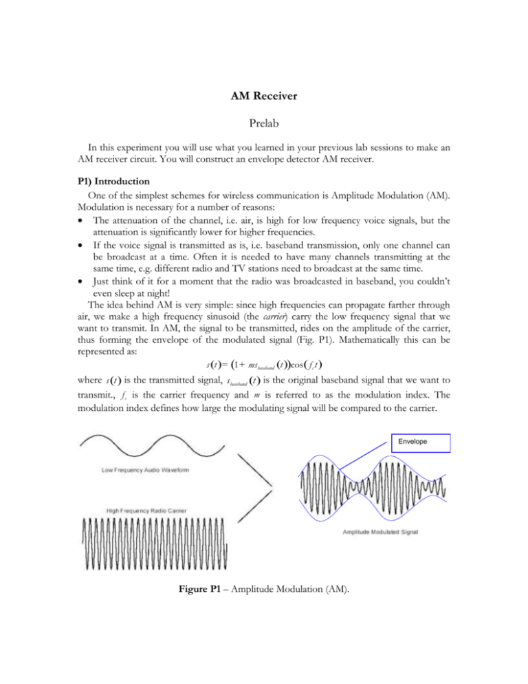
AM Receiver Prelab In this experiment you will use what you learned in your previous lab sessions to make an AM receiver circuit. You will construct an envelope detector AM receiver. P1) Introduction One of the simplest schemes for wireless communication is Amplitude Modulation (AM). Modulation is necessary for a number of reasons: The attenuation of the channel, i.e. air, is high for low frequency voice signals, but the attenuation is significantly lower for higher frequencies. If the voice signal is transmitted as is, i.e. baseband transmission, only one channel can be broadcast at a time. Often it is needed to have many channels transmitting at the same time, e.g. different radio and TV stations need to broadcast at the same time. Just think of it for a moment that the radio was broadcasted in baseband, you couldn’t even sleep at night! The idea behind AM is very simple: since high frequencies can propagate farther through air, we make a high frequency sinusoid (the carrier) carry the low frequency signal that we want to transmit. In AM, the signal to be transmitted, rides on the amplitude of the carrier, thus forming the envelope of the modulated signal (Fig. P1). Mathematically this can be represented as: s (t ) = (1 + ms baseband (t ))cos ( f c t ) where s (t ) is the transmitted signal, s baseband (t ) is the original baseband signal that we want to transmit., f c is the carrier frequency and m is referred to as the modulation index. The modulation index defines how large the modulating signal will be compared to the carrier. Envelope Figure P1 – Amplitude Modulation (AM). P2) Frequency Domain Representation In order to better understand how amplitude modulation works, let’s analyze the modulation in frequency domain. Basically, multiplying the input signal by the carrier signal results in the frequency content of the input signal to be shifted to around the carrier frequency (Fig. P2). As explained before, the original baseband signal may not be able to propagate well through the channel, but frequencies near carrier frequency will. By multiplying the signal with the carrier, its frequency content moves to around the carrier frequency and can thus propagate through the channel efficiently. Assume there is a frequency band, say 20 times the bandwidth of the original signal, that can propagate through the channel efficiently. This frequency band can be divided between 10 different stations transmitting with AM. This can be done by assigning each of them a unique carrier signal and sufficient spacing between the carrier frequencies (Fig P3). This procedure is referred to as multiplexing. f fc f f fc Figure P2 – left – The original baseband input signal frequency content, middle – The frequency content of the result of multiplying the input and carrier signal, right – The AM transmitted signal, note that the constant carrier term appears as a delta function. Station 1 Station 2 Station 3 Station 4 fc1 fc2 fc3 fc4 f Figure P3 – left – The original baseband input signal frequency content of four stations, right – Multiplexing the four stations using different carrier frequencies. The spacing between carriers is chosen such that the frequency contents won’t overlap. P3) AM Receiver Circuit There are different ways to demodulate an AM signal and recover the transmitted waveform. Probably the simplest way is to use an envelope detector. As you saw in the introduction, the modulating signal rides on carrier amplitude and thus forms the envelope of the transmitted signal. The envelope detector recovers the transmitted signal riding on the carrier by extracting the envelope of the received signal. The structure of a typical envelope detector receiver is shown in figure P4. Tuned Filter RF Amplifier Peak Detector Audio Amplifier Figure P4 – Structure of a typical AM receiver The envelope detector that you will use in this experiment is referred to as the peak envelope detector. It consists of a diode and an RC circuit. This cheap, easy to build detector is one of the main reasons of popularity of AM in early radios. The receiver will be quite inexpensive and thus affordable to a larger number of people. The structure of the peak detector is shown in figure P5. Assuming that the diode is ideal and that the initial transient response is passed, this is how the detector essentially works: Assume that the carrier is at one of its peaks (note that the peak magnitude is controlled by the modulating audio signal). At this point, since we assumed the transient is passed, capacitor C is charged all the way up to the voltage magnitude of current peak, so the diode is off (the voltage drop the diode is zero). So the RC circuit will now consist of a capacitor charged to an initial voltage. Hence, the capacitor’s voltage will start to decrease exponentially. The diode will remain off till the input signal to the detector becomes greater than the capacitor voltage. At this point the diode will start conducting and the capacitor voltage follows the input voltage till the next peak (Fig. P5). The choice of the value of resistor R is crucial for the desired performance of the detector. If R is chosen very small, the capacitor will fully discharge thus there will be bigger ripples in the detected envelope. On the other hand if R is chosen very large, another phenomenon called failure to follow distortion occurs. This is best shown in figure P6. As you can see, the capacitor discharges so slowly that its voltage remains greater than a number peaks in the input signal. So, the circuit misses on a few peaks and thus outputs a distorted detected envelope. Practically, to avoid these problems, the value of R should be chosen such that it will meet the following criterion: 2p f m < 1 = 2p f c RC (1) where, f c is the carrier frequency and f m is the highest frequency present in the modulating audio signal. The ripple can be approximated by: Vr = V p (1 - e - 1 f RC ) , where V p is the peak value c of the input voltage. Envelope Detected Envelope Vout Figure P5 – left – The peak envelope detector circuit. right – An AM signal, its envelope (dashed) and its envelope detected by the circuit on the left (heavy solid). Note the ripples. Detected Envelope Missed peak Figure P6 – Failure to follow distortion. The time constant of the RC circuit has been very large, so two peaks have been missed and the detected envelope is distorted. 1) The Receiver Circuit The AM Receiver circuit consists of 4 major parts (Fig. 1): 1. The tuned tank 2. The RF amplifier 3. The envelope detector 4. The audio amplifier To build the circuit proceed as follows: 1. Choose the values of R3 and C2 to satisfy equation 1. Choose R3 to be in the range of 2-10 KW. 2. Connect the envelope detector circuit. 3. On the signal generator, generate an AM signal with modulation index of 0.5, amplitude of 5Vpp, carrier frequency of 100KHz and modulating tone frequency of 1KHz. 4. Apply the generated AM signal to the circuit. And observe the output on the oscilloscope. 5. Make sure your circuit is working properly. 6. Construct the amplifier circuit on another part of the breadboard but don’t connect it to the envelope detector. 7. Reduce the amplitude of your synthetic AM signal to 100mVpp. 8. Apply the signal to the amplifier and make sure it’s working as required. 9. Determine the resistor values for the audio amplifier stage such that it will have a gain of 10. 10. Connect the audio amplifier stage and the speaker. 11. Increase the amplitude of the AM signal to 0.5Vpp. 12. Connect the output of the detector to the audio amplifier through the potentiometer and apply the AM signal to the detector. 13. Check if your circuit works fine. Can you hear a clear sound? 14. Connect the tank and the RF amplifier to the rest of the circuit. 15. Set the amplitude of the AM signal back to 100mVpp and test your completed circuit. Figure 2 – AM Receiver circuit: 1. Tuned tank, 2. RF amplifier, 3. Envelope Detector, 4. Audio Amplifier

