04_Lab_System
advertisement
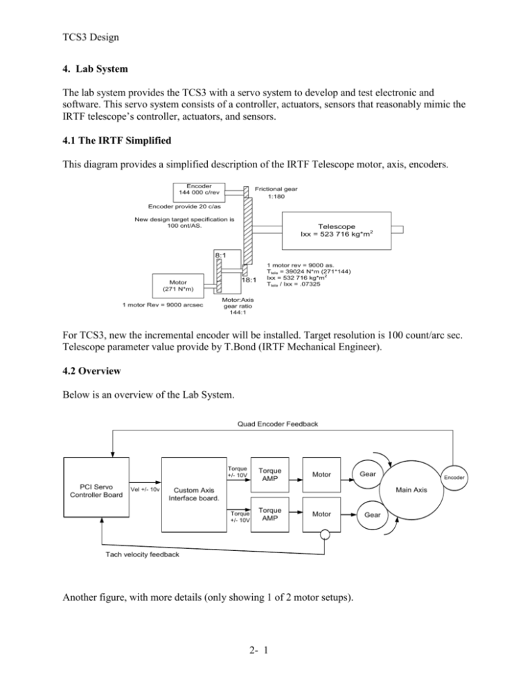
TCS3 Design 4. Lab System The lab system provides the TCS3 with a servo system to develop and test electronic and software. This servo system consists of a controller, actuators, sensors that reasonably mimic the IRTF telescope’s controller, actuators, and sensors. 4.1 The IRTF Simplified This diagram provides a simplified description of the IRTF Telescope motor, axis, encoders. Encoder 144 000 c/rev Frictional gear 1:180 Encoder provide 20 c/as New design target specification is 100 cnt/AS. Telescope Ixx = 523 716 kg*m2 8:1 18:1 Motor (271 N*m) 1 motor Rev = 9000 arcsec 1 motor rev = 9000 as. Ttele = 39024 N*m (271*144) Ixx = 532 716 kg*m2 Ttele / Ixx = .07325 Motor:Axis gear ratio 144:1 For TCS3, new the incremental encoder will be installed. Target resolution is 100 count/arc sec. Telescope parameter value provide by T.Bond (IRTF Mechanical Engineer). 4.2 Overview Below is an overview of the Lab System. Quad Encoder Feedback Torque +/- 10V PCI Servo Controller Board Vel +/- 10v Torque AMP Motor Gear Encoder Main Axis Custom Axis Interface board. Torque +/- 10V Torque AMP Motor Tach velocity feedback Another figure, with more details (only showing 1 of 2 motor setups). 2- 1 Gear TCS3 Design < slew limit x4 < stop limit x4 < brake limit x4 < Tach output x4 Tachometer & limit Switch Function using Computer: encorder Intepolator D/A resolution DIO board < Encoder A,B,C Motor Amplifier > Cmd > Enable < Fault Encoder T3 Computer Power Supply T3 Electronics Power Supply > ACC-8D > AI brd >TOP brd < TacOut(v) Servo Motor Axis Interface Vel Cmd> ACC-8D Option-P (terminal brakeout board) Turbo PMAC PCI Lite JMAC to 8D Cable Gear TO Panel Electronics Gear ACC-8D-Opt-6 Quad Encoder Opto-Isolation Board Encoder < Encoder A,B,C 4.3 Computer & Servo Controller The PC is a standard x86/PCI system running a Linux OS. The servo controller is the Turbo PMAC PCI Lite in the following configurations. This is the target configuration for the IRTF summit system: Turbo PMAC PCI Lite (4 Axis Stepper and/or Direct PWM Controller) 400-603657-TRx OPT-5C0, 5C0-0TURBO-OPT, Default CPU-speed/memory config. OPT-2, 302-603657-OPT , On-board 8Kx16 Dual Ported RAM for PCI or USB 302-603657-OPT ACC-8D, 3D0-602205-10x , PMAC(1) 4-channel breakout board, monolithic terminal block, IDC headers (must specify Opt-P or V) 3D0-602205-10x OPT-P, 30P-0ACC8D-OPT, 40 cm (16 inch) cable with 60-pin IDC connector for ACC-8D OPT-6, 306-0ACC8D-OPT, Quad 3-channel encoder isolate board with 4 40-cm (16 inch) cables to ACC8D,8E,8F ACC-28B, 3A0-602678-10x, 2-channel A/D converter board, 16-bit resolution, 15-bit repeatability (Must select Option 2A or 2B)** OPT-2B, 3B2-ACC28A-OPT, 12-pin input terminal block OPT-1, 301-00028B-OPT, Additional on board 2-channels A/D converter ACC-22, 3A0-00WARR-000, Extended warranty, to 2 years from data of purchase ACC- 9WPRO, 3A0-09WPRO-35x, PMAC Executive Professional Suite for Windows 98/ME/2000 (32bit) 3A0-09WPRO-35x 4.4 Mechanical Design The mechanical design concept was developed by T.Bond. T.Bond’s notes on the design concept can be found at: 2- 2 TCS3 Design http://irtfweb.ifa.hawaii.edu/~tcs3/systems/tcs3/0309_Design/04_Lab_System/mechanical_docs 4.4.1 Notes on gearing ratio and encoder resolution. The Lab Motors will match the following IRTF parameters: 9000 as/r on its motor shaft (900 000 c/r) Provides 100 c/as inc encoder on main shaft (TCS3 target resolution). Our model: 9000 as/r on motor staff. 1:4 gearing provides 2250 as/r on main staff. Uses 230 400 c/r encoder on main staff for 102.4 c/as inc encoder Note: The modeling work performed after the lab motor fabrication indicates that 20 c/as is sufficient for the IRTF, therefore the target 100c/as design was reduce to the resolution of the IRTF’s present encoders of 20c/as. The lab motor system assumes 20c/as on the main shaft. 4.4.3 Notes on inertia, motor torque requirements The fax summaries the inertia design for the Lab Motors. In general, we scaled the model based on Torque (T in N*m) , Inertia (Ixx in kg*m2) using the acceleration ratio (A in rad/s2). T = Ixx * A For the model, we select 0.393 n*m Torque motors, adjusted the gearing to 4:1, and calculated the Ixx for the LabMotor Load plate. 4.4.5 The Mechanical Design and Assembly Mechanical Drawings for machine shop fabrication and assembly are located at: http://irtfweb.ifa.hawaii.edu/~tcs3/systems/tcs3/0309_Design/04_Lab_System/mechanical_docs 4.5 Lab Motor Electronics Electronics Documentation is located at http://irtfweb.ifa.hawaii.edu/~tcs3/systems/tcs3/0309_Design/04_Lab_System/electronics_doc 4.6 Lab System Pseudo-Tachometers. It was difficult matching the specification of the tachometer used at the IRTF. Off-the-Shelf tachometer could not meet the torque, size, resolution requirements for the lab system. In the end, we decided to simulation the tachometer using an encoder on the motor shaft. A PC would output velocity using a D/A to represent the tachometers. The PC is also able to maintain an absolute position, therefore can provide limit switch and APE function for the lab system. 2- 3 TCS3 Design In order to meet the tachometer requirement, the following pseudo-tachometers will be implemented: 1. Use Heidenhain ERN100 Encoder and IK220 PCI-based counter board each axis. Total of 4 encoders and 2 IK220. Resolution of the ERN100+IK220 = (3600 line/rev * 4096 interpolation = 15782400 counts/rev). 2. A computer is used to read the counts and calculate velocity. The LinuxOS with a 2.6 kernel is used to perform a approx. 333 Hz calculation loop. 3. The computer also need a PCI based Analog and Digital IO: a. An ADLINK PCI-6208V 8-channel 16-bit Voltage Output D/A card is a PCI peripheral used to output the tachometer voltage (4 D/A channels) b. An ADLINK PCI-7248 48-bit digital IO Card is a PCI peripheral used to provide limit switch output to simulate the slew, stop and brake limit for each axis. 3 limits * 4 sets = 12 Digital output used. 4. The computer will need a PCI DIO boards in order to provide limits switch output (slew, stop, and brake limit for each axis). Total of 12 DO is needed. 5. The calculation loop is to be performed at 150Hz (minimum). The software for the Pseudo-tachometers is called simtac. Its source and binaries are located in /home/tcs3/src/tcs3/simtac. Using tachometer on the motor shaft is designed in a servo system to provide the controller with a velocity senor with less latency that the encoder used on the main shaft. It was realized after the pseudo-tachometer was design and build, that this design actually provides velocity sensor with greater latency that the main staff encoder. Thus pseudo-tachometers purpose is to provide the Lab System with tachometer inputs similar to actual telescope tachometers. 4.6 Notes on Lab Motor Configuration From engineering data obtain from the telescope (see history/0312) we determined the following: Tracking West Tracking East West Motor East Motor -0.3 +Err 0.3 AMP Voltage 0.1 0.1 TAC output West Motor East Motor -0.3 +0.3 + Err AMP Voltage -0.1 -0.1 TAC output Tracking North Tracking South North Motor South Motor -0.3 +Err 0.3 AMP Voltage 0.1 0.1 TAC output North Motor South Motor -0.3 +0.3 + Err AMP Voltage -0.1 -0.1 TAC output Below is a summary diagram of the lab motors direction to mimic the IRTF polarity and direction: 2- 4 TCS3 Design West +HA -RA West 12.59 deg/Rev 14808 as/Rev West Amp (-Volts) HA Axis East -HA +RA North +Dec DEC Axis 1 rev 230 400 cnts 11520 as 3.1475 deg 1 rev 230 400 cnts 11520 as 3.1475 deg 20 cnt/as 20 cnt/as North East 12.59 deg/Rev 14808 as/Rev East Amp (+Volts) North Amp (-Volts) 2- 5 South -Dec South South Amp (+Volts) TCS3 Design 4.7 Budget Estimated Qty Cost Servo Simulator Motor/Amps/PS Gear box / Inc. Encoders Mechanical Hardware Shop Labor 5 2 2 40 Subtotal 1000 1000 2000 75 5000 2000 4000 3000 14000 ACTUAL Item Motor/Amps/PS/Encoder Maxon Gurley Heidenhain Item Qty $ea SubT $ Z661616 -Motor(5each)/Amp(5each) 1 1951.00 Z661617 - Encoders (2) 1 935.00 Z663104 - ERN1080(2),IK220 PCI(2) - tach1 encoder3675.50 1951.00 935.00 3675.50 0.00 0.00 Mechanical Hardware Stock Drive Products Nordex McMaster-Carr Kaman Industrial Kulicke &Soffa Industries Z666225 - Gears, Coupling, etc Z666224 - Shafts, etc Z666223 - Screw Z667248 - Trantorque (6) Z668970 - Spindle Brg 1 1 1 1 1 994.00 73.00 100.00 242.00 1322.40 994.00 73.00 100.00 242.00 1322.40 Electronics/Computers Circuit Specialist Z661618 - PCI-7248 (DIO), PC-6208(D/A) 1 770.00 770.00 Machine Shop Royal Metals Machine Shop Labor Z668977-Aluminum Plates (various) 125 hours was Randy's Estimate 754.00 754.00 74.43 10122.48 10876.48 1 136 Total 2- 6 $20,939 6561.50 2731.40


