Tutorial_Sheet_3
advertisement

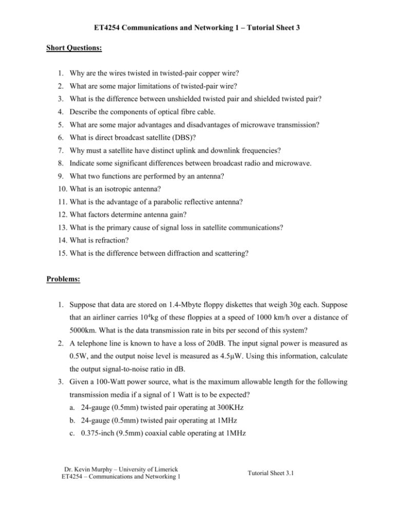
ET4254 Communications and Networking 1 – Tutorial Sheet 3 Short Questions: 1. Why are the wires twisted in twisted-pair copper wire? 2. What are some major limitations of twisted-pair wire? 3. What is the difference between unshielded twisted pair and shielded twisted pair? 4. Describe the components of optical fibre cable. 5. What are some major advantages and disadvantages of microwave transmission? 6. What is direct broadcast satellite (DBS)? 7. Why must a satellite have distinct uplink and downlink frequencies? 8. Indicate some significant differences between broadcast radio and microwave. 9. What two functions are performed by an antenna? 10. What is an isotropic antenna? 11. What is the advantage of a parabolic reflective antenna? 12. What factors determine antenna gain? 13. What is the primary cause of signal loss in satellite communications? 14. What is refraction? 15. What is the difference between diffraction and scattering? Problems: 1. Suppose that data are stored on 1.4-Mbyte floppy diskettes that weigh 30g each. Suppose that an airliner carries 104kg of these floppies at a speed of 1000 km/h over a distance of 5000km. What is the data transmission rate in bits per second of this system? 2. A telephone line is known to have a loss of 20dB. The input signal power is measured as 0.5W, and the output noise level is measured as 4.5μW. Using this information, calculate the output signal-to-noise ratio in dB. 3. Given a 100-Watt power source, what is the maximum allowable length for the following transmission media if a signal of 1 Watt is to be expected? a. 24-gauge (0.5mm) twisted pair operating at 300KHz b. 24-gauge (0.5mm) twisted pair operating at 1MHz c. 0.375-inch (9.5mm) coaxial cable operating at 1MHz Dr. Kevin Murphy – University of Limerick ET4254 – Communications and Networking 1 Tutorial Sheet 3.1 ET4254 Communications and Networking 1 – Tutorial Sheet 3 d. 0.375-inch (9.5mm) coaxial cable operating at 25MHz e. optical fiber operating at its optimal frequency 4. Coaxial cable is a two-wire transmission system. What is the advantage of connecting the outer conductor to ground? 5. Show that doubling the transmission frequency or doubling the distance between transmitting antenna and receiving antenna attenuates the power by 6dB. 6. It turns out that the depth in the ocean to which airborne electromagnetic signals can be detected grows with the wavelength. Therefore, the military got the idea of using very long wavelengths corresponding to about 30Hz to communicate with submarines throughout the world. It is desirable to have an antenna that is about one-half wavelength long. How long would that be? 7. Stories abound of people who receive radio signals in fillings in their teeth. Suppose you have one filling that is 2.5mm (0.0025m) long that acts as a radio antenna. That is, it is equal in length to one-half the wavelength. what frequency do you receive. 8. A microwave transmitter has an output of 0.1W at 2GHz. Assume that this transmitter is used in a microwave communications system where the transmitting and receiving antennas are parabolas, each 1.2m in diameter. a. What is the gain of each antenna in decibels? b. Taking into account antenna gain, what is the effective radiated power of the transmitted signal? c. If the receiving antenna is located 24 km from the transmitting antenna over a free space path, find the available signal power out of the receiving antenna in dBm units. 9. Determine the height of an antenna for a TV station that must be able to reach customers 80km away. (HINT: d = 3.57 Kh with K = 4/3) Dr. Kevin Murphy – University of Limerick ET4254 – Communications and Networking 1 Tutorial Sheet 3.2 ET4254 Communications and Networking 1 – Tutorial Sheet 3 Answers: Short Questions 1. The twisting of the individual pairs reduces electromagnetic interference. For example, it reduces crosstalk between wire pairs bundled into a cable. 2. Twisted pair wire is subject to interference, limited in distance, bandwidth, and data rate. 3. Unshielded twisted pair (UTP) is ordinary telephone wire, with no form of electromagnetic shielding around the wire. Shielded twisted pair (STP) surrounds the wire with a metallic braid or sheathing that reduces interference. 4. Optical fiber consists of a column of glass or plastic surrounded by an opaque outer jacket. The glass or plastic itself consists of two concentric columns. The inner column called the core has a higher index of refraction than the outer column called the cladding. 5. Point-to-point microwave transmission has a high data rate and less attenuation than twisted pair or coaxial cable. It is affected by rainfall, however, especially above 10 GHz. It is also requires line of sight and is subject to interference from other microwave transmission, which can be intense in some places. 6. Direct broadcast transmission is a technique in which satellite video signals are transmitted directly to the home for continuous operation. 7. A satellite must use different uplink and downlink frequencies for continuous operation in order to avoid interference. 8. Broadcast is omnidirectional, does not require dish shaped antennas, and the antennas do not have to be rigidly mounted in precise alignment. 9. The two functions of an antenna are: (1) For transmission of a signal, radio-frequency electrical energy from the transmitter is converted into electromagnetic energy by the antenna and radiated into the surrounding environment (atmosphere, space, water); (2) for reception of a signal, electromagnetic energy impinging on the antenna is converted into radio-frequency electrical energy and fed into the receiver. 10. An isotropic antenna is a point in space that radiates power in all directions equally. Dr. Kevin Murphy – University of Limerick ET4254 – Communications and Networking 1 Tutorial Sheet 3.3 ET4254 Communications and Networking 1 – Tutorial Sheet 3 11. A parabolic antenna creates, in theory, a parallel beam without dispersion. In practice, there will be some beam spread. Nevertheless, it produces a highly focused, directional beam. 12. Effective area and wavelength. 13. Free space loss. 14. Refraction is the bending of a radio beam caused by changes in the speed of propagation at a point of change in the medium. 15. Diffraction occurs at the edge of an impenetrable body that is large compared to the wavelength of the radio wave. The edge in effect become a source and waves radiate in different directions from the edge, allowing a beam to bend around an obstacle. If the size of an obstacle is on the order of the wavelength of the signal or less, scattering occurs. An incoming signal is scattered into several weaker outgoing signals in unpredictable directions. Problems 1. Elapsed time = (5000 km)/(1000 km/hr) = 5 hours = 18,000 seconds Amount of data per diskette = 1.4 x 10242 x 8 = 11.74 x 106 bits/diskette Number of diskettes = (107 g)/(30 g/diskette) = 333333 diskettes Data transfer rate = 11.74× 106 bits diskette x 333333diskettes = 217Mbps 18,000seconds 2. 10 log (Po/Pi) = –20dB; Therefore, Po/Pi = 0.01 For Pi= 0.5 Watt, Po = 0.005 Watt SNR = 0.005/(4.5 x 10-6) = 1.11 x 10³ SNRdB = 10 log (1.11 x 10³) = 30 dB 3. The allowable power loss is 10 × log 100 = 20 dB From Figure 4.3, the attenuation is about 13 dB per km. a. Length = (20 dB)/(13 dB per km) = 1.5 km b. Length = (20 dB)/(20 dB per km) = 1 km c. Length = (20 dB)/(2.5 dB per km) = 8 km d. Length = (20 dB)/(10 dB per km) = 2 km Dr. Kevin Murphy – University of Limerick ET4254 – Communications and Networking 1 Tutorial Sheet 3.4 ET4254 Communications and Networking 1 – Tutorial Sheet 3 e. Length = (20 dB)/(0.2 dB per km) = 100 km 4. An electromagnetic wave cannot penetrate an enclosing conductor. If the outer conductor of a coaxial cable is everywhere held at ground potential, no external disturbance can reach the inner, signal-carrying, conductor. 5. From Equation 4,2, the ratio of transmitted power to received power is Pt/P r = (4πd/λ)2 If we double the frequency, we halve λ, or if we double the distance, we double d, so the new ratio for either of these events is: Pt/Pr2 = (8πd/λ)2 Therefore: 10 log (Pr /Pr2) = 10 log (22 ) = 6 dB 6. We have λf = c; in this case λ × 30 = 3 × 10⁸ m/sec, which yields a wavelength of 10,000 km. Half of that is 5,000 km which is comparable to the east-to-west dimension of the continental U.S. While an antenna this size is impractical, the U.S. Defense Department has considered using large parts of Wisconsin and Michigan to make an antenna many kilometers in diameter. 7. λ = 2 × 2.5 × 10 –3 m = 5 × 10⁻³ m f = c/λ = (3 × 10⁸ m/sec)/( 5 × 10⁻³ m) = 6 × 10¹⁰ Hz = 60 Ghz 8. a. G = 7A/λ 2 = 7Af2 /c 2 = (7 × π × (0.6) 2 × (2×109 )2 ]/(3 × 108 )2 = 351.85 GdB = 25.46 dB b. 0.1 W x 351.85 = 35.185 W c. Use LdB = 20 log (4π) + 20 log (d) + 20 log (f) – 20 log (c) – 10 log(Gr ) – 10 log (Gt) LdB = 21.98 + 87.6 + 186.02 – 169.54 – 25.46 – 25.46 = 75.14 dB The transmitter power, in dBm is 10 log (100) = 20. The available received signal power is 20 – 75.14 = –55.14 dBm 9. For radio line of sight, we use d = 3.57 Kh , with K = 4/3, we have 802 = (3.57)2 × 1.33 × h. Solving for h, we get h = 378 m. (Aside:- Three rock mountain in Ireland is one location for RTE amongst other transmitters. RTE operate a large transmitter close to its peak at 450 metres above ordnance datum (above sea level)) Dr. Kevin Murphy – University of Limerick ET4254 – Communications and Networking 1 Tutorial Sheet 3.5


