Keywords: knee, fracture reduction, anatomical adaptive
advertisement
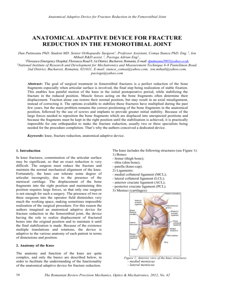
Anatomical Adaptive Device for Fracture Reduction in the Femorotibial Joint ANATOMICAL ADAPTIVE DEVICE FOR FRACTURE REDUCTION IN THE FEMOROTIBIAL JOINT Dan Putineanu PhD. Student MD. Senior Orthopaedic Surgeon 1, Professor Assistant, Comşa Stanca PhD. Eng. 2, Ion Mihail R&D assist. 2, Pacioga Adrian Eng2., 1 Floreasca Emergency Hospital, Floreasca Road 8, 1st District, Bucharest, Romania, E-mail: dputineanu2002@yahoo.co.uk, 2 National Institute of Research and Development for Mechatronics and Measurement Technique 6-8 Pantelimon Road, 2nd District, Bucharest, Romania, 021631, E-mail: stanca_comsa@yahoo.com, ion.mihail@yahoo.com, pacioga@yahoo.com Abstract: The goal of surgical treatment in femorotibial fractures is a perfect reduction of the bone fragments especially when articular surface is involved, the final step being realization of stable fixation. This enables less painful motion of the knee in the initial postoperative period, while stabilizing the fracture in the reduced position. Muscle forces acting on the bone fragments often determine their displacement. Traction alone can restore their normal position, but may result in an axial misalignment, instead of correcting it. The options available to stabilize these fractures have multiplied during the past few years, but the main problem remains the correct positioning of the bone fragments in the anatomical position, followed by the use of screws and implants to provide greater initial stability. Because of the large forces needed to reposition the bone fragments which are displaced into unexpected positions and because the fragments must be kept in the right position until the stabilisation is achieved, it is practically impossible for one orthopaedist to make the fracture reduction, usually two or three specialists being needed for the procedure completion. That’s why the authors conceived a dedicated device. Keywords: knee, fracture reduction, anatomical adaptive device. 1. Introduction In knee fractures, comminution of the articular surface may be significant, so that an exact reduction is very difficult. The surgeon must reduce the fracture and maintain the normal mechanical alignment of the knee. Fortunately, the knee can tolerate some degree of articular incongruity, due to the presence of the meniscal cartilage. The displacement of the bone fragments into the right position and maintaining this position requires large forces, so that only one surgeon is not enough for such a surgery. The presence of two or three surgeons into the operator field diminishes very much the working space, making sometimes impossible realization of the surgical procedure. For this reason the authors imagined an anatomical adaptive device for fracture reduction in the femorotibial joint, the device having the role to realize displacement of fractured bones into the original position and to maintain it until the final stabilization is made. Because of the existence multiple translations and rotations, the device is adaptive to the various anatomy of each patient in terms of dimensions and position. The knee includes the following structures (see Figure 1): 1) Bones: - femur (thigh bone); - tibia (shin bone); - patella (knee-cap). 2) Ligaments: - medial collateral ligament (MCL); - lateral collateral ligament (LCL); - anterior cruciate ligament (ACL); - posterior cruciate ligament (PCL). 3) Menisci (cartilages): 2. Anatomy of the Knee The anatomy and function of the knee are quite complex, and only the basics are described below, in order to facilitate the understanding of the functionality of the anatomical adaptive device for fracture reduction. 16 Figure 1: Anterior view of the knee structures - medial meniscus - lateral meniscus The Romanian Review Precision Mechanics, Optics & Mechatronics, 2012, No. 42 Anatomical Adaptive Device for Fracture Reduction in the Femorotibial Joint 4) Joint capsule The glossary at the end of the article explains the medical terms which are used in this paper. The tibial plateau articulates with the femoral condyles, and the patellofemoral groove (located anteriorly between the femoral condyles) accepts the patella. The tibia and patella do not articulate. The gliding motion of the patella across the femur allows smooth extension at the knee and increases the mechanical advantage of the quadriceps. The extra-articular muscle-tendon units include the quadriceps and patellar tendons (responsible for knee extension), medial and lateral hamstrings (chiefly responsible for knee flexion), gastrocnemius muscle, popliteal ligament and iliotibial band (see Figure 2). likely to cause a tibial plateau fracture as the weight drives the femur into the tibia. Twisting and bending injuries are more common with sports and these can cause any of the supracondylar fractures depicted above. In the elderly, supracondylar fractures and plateau fractures are considered fragility fractures. These fractures may have occurred as a result of osteoporosis [2]. a. Patellar fractures b. Supracondy lar fractures c. Tibial plateau and fibula fractures Figure 2.Anterior and posterior views of the muscles associated with the knee The extra-articular ligamentous structures include the tibial and fibular collateral ligaments (see Figure 1). These ligaments act as the principal extra-articular static stabilizing structures (i.e., they provide stability for the medial and lateral aspects of the knee). The intra-articular structures include the medial and lateral menisci and the anterior and posterior cruciate ligaments (see Figure 1). The menisci are fibrocartilaginous wedges that rim and cushion each femorotibial articulation. The anterior and posterior cruciate ligaments provide stability for the knee joint [1]. 3. Knee Fracture Types and Treatment Fractures of the knee are very complex and often involve articular surfaces. Fractures may occur in the patella, femoral condyles, tibial plateau or fibula (see Figure 3.a, b, and c) and can be displaced or undisplaced. Large forces are required to fracture the knee joint. These may be the result of a direct force (e.g. being hit by the bumper bar of a car, or getting a stop kick to the knee) or an indirect force (e.g. a sudden contraction of the thigh muscle can fracture the patella). The two main mechanisms of patellar fracture are direct trauma to the anterior aspect of the knee or a powerful contraction of the quadriceps muscle (transverse, upper pole and lower pole fractures). Falls from a height would be more Figure 3: Knee fracture types For undisplaced fractures of any part of the knee, immobilization of the knee is an option. This is the normal treatment for knee fractures, unless ligament reconstruction surgery is also needed. The cast is applied from thigh to ankle leaving the foot out of the cast. If the cast treatment is for an undisplaced supracondylar fracture or a tibial plateau fracture, the knee is usually held in 45 degrees flexion inside the cast. Undisplaced fractures of the kneecap are rare but may be treated in a cast with the knee straight. Cast treatment has disadvantages because it makes full recovery longer (cast immobilization is continued until healing has occurred) and the fracture fragments may not be accurately reduced or may displace during the healing period leading to malunion. The most popular method of surgical treatment of knee fractures is the opened reduction with internal fixation. This means that the fracture site is exposed through an incision in the skin (open), the fracture fragments are moved back into the correct position (reduction) and then held in place by metal implants such as pins, screws and plates (fixation). The fixation devices are left on the bone and the wound is closed [2]. The main problem in this case is the displacement of the bone fragments into the normal position, because as described above, in the knee joint the muscles and ligaments tends to move the fragments in to unexpected positions once the bone has been broken. Large forces are often needed in order to bring back into original position these fragments and maintain this position until The Romanian Review Precision Mechanics, Optics & Mechatronics, 2012, No. 42 17 Anatomical Adaptive Device for Fracture Reduction in the Femorotibial Joint the fixation is completed. That’s why the specialists from INCDMTM in collaboration with a Senior Orthopaedic Surgeon from Floreasca Emergency Hospital designed and manufactured the anatomical adaptive device for fracture reduction in the femorotibial joint which is described below. 4. Description of the device reduced, paying particular attention to the joint surface. If there are small bone fragments, these must be removed. Only the large fragments are taken into account and the size of these fragments should allow screwing the threaded K wire with diamond tip and single end (see Figure 5). If parts of the joint surface which are broken were pushed inside the bone, these fragments need to be lifted up, or elevated, and held in position until fixation is done. The conception of the device and its components are presented in figure 4. Figure 5: Kirschner threaded wire with diamond tip and single end Figure 4: Anatomical adaptive device for fracture reduction in the femorotibial joint The device consists of the following main items: 1. Base plate. Through it, the device is rigidly attached to the operating table, and its length ensures the possibility of adaptation to the specific dimensions of the patient anatomy. 2. Oval holes. They are provided in order to make the necessary adjustments according to the joint size. 3. Knob to adjust the distance between the two pillars according to the joint size. By loosening those knobs, the orthopaedist moves the two pillars depending on the joint size. 4. Vertical pillar. It sustains the orientation (X, Y, Z) and lock in position mechanism. 5. Kirschner threaded wire with diamond tip and single end. The threaded end is inserted in the bone fragment which must be displaced in to the original position. 6. Knob for adjusting the distance on the X axis direction. Using this knob, the surgeon moves (rotation, translation) the bone fragment in the desired position on X axis direction and locks the K threaded wire in the desired position. 7. Knob for adjusting the distance on the Y axis direction. 8. Knob for adjusting the distance on the Z axis direction. The surgical protocol depends on the anatomy of the fracture, but in most cases the broken bone is exposed. Exposing a fracture means that an incision is made and enough of the tissue surrounding the fracture is moved aside so that the fracture can be seen good enough to repair it. The fracture fragments are then 18 First, the anatomical adaptive device is mounted on the operating table and after securing it the surgeon adapts the distance between the two vertical pillars according to the patient size and locks them into position. After the K wire is inserted into the bone fragment which must be repositioned, the surgeon uses the other end of the wire which acts as a joystick. The orthopaedist uses the four degrees of freedom of the anatomical adaptive device (three rotations and one translation) in order to move the bone fragment into the functional position and then the fragment is locked in this position using the dedicated knobs of the device. Sometimes a pointed reduction forceps can be useful, as rotational control of the bone is also needed. A special attention is accorded to any intra-articular fragments, which must be reduced accurately and fixed with pins or screws in order to ensure that the joint surface is restored to smoothness. After bone fragment positioning, before definitive fixation is inserted, the fracture is clamped. Usually, one to two K-wires are inserted for provisional fixation. In this stage, it is very important to check the biomechanical axis of the lower limb. The normal biomechanical axis follows a line from the center of the femoral head, through the center of the proximal tibia and then through the center of the ankle joint. This axis should be checked intraoperatively, to give an approximate estimate of the axis (see Figure 6). Figure 6: Checking the biomechanical axis of the lower limb The Romanian Review Precision Mechanics, Optics & Mechatronics, 2012, No. 42 Anatomical Adaptive Device for Fracture Reduction in the Femorotibial Joint Before definitive fixation, the correct position of the nail/plate and the rotation of the femur must also be verified. Not only the biomechanical axis must be restored, but care should be taken to ensure that there is no accidental rotation between the proximal and the distal end of bone [3]. The final fixation can be made using nail or plates. Regardless the type of fixation used (nails or plates), the fixing device should extend up/down to the intact part of the bone and fixed with transverse screws. The fractured part of the bone is also fixed to the nail/plate. Thus all fracture fragments are held immobile and in good position by the fixing device and fixation is obtained above and below the fracture site. If there are more bone fragments (comminuted fracture), this reduction procedure is repeated as many times as necessary, for each pair of bone fragments which are displaced from their original position. If necessary, bone graft can be used to add support for the depressed fragments [4]. The manufactured functional model of the anatomical adaptive device for fracture reduction in the femorotibial joint is presented in figure 7.a. and a detail with the orientation and lock into position mechanism is shown in figure 7.b. a. Overall view b. Detail of the orientation mechanism Figure 7: Functional model of the anatomical adaptive device for fracture reduction in the femorotibial joint The device is all stainless steel, and was used by the M.D. of the research team (who is a senior orthopaedic surgeon) for some experiments on cadavers. The obtained results were very promising opening the way for the clinical use of the device. During these experiments, studies were made in order to see if this adaptive device can be utilized for indirect reduction of the fracture fragments with minimal exposure (minimally invasive technique). According to this technique, the fracture site is not entirely exposed, the fixing device being slid up under the muscle and the screws being inserted through small incisions into the skin, so that the blood supply is not disturbed. The results were also satisfactory, but in this case, the experiments were carried out under image intensifier guidance, producing high quality intraoperative images in order to ensure correct reposition of the bone fragments. Considering these results, the research team aims to patent the device and to obtain medical certification, so that that it could be soon used into current medical practice. 5. Glossary Anterior - Situated at the front; Extension - Moving a limb so that the two posts are straightened; Flexion - Moving a limb so that the two parts are bent; Fracture - Broken or cracked bone; Comminuted (fracture): A fracture in which the bone has broken into a number of pieces; Invasive (procedure): when a break in the skin is created and there is direct contact with the mucosa, or internal body cavity; Lateral - A position away from the centre of the body (opposite to "medial"); Medial - A position toward the centre of the body; Posterior - Situated at the back; Meniscus - Cartilage inside knee joint; Rotation - Twisting. 6. References [1] Howard, B., Tandeter, Pesach Shvartzman: “Acute Knee Injuries: Use of Decision Rules for Selective Radiograph Ordering” American Family Physician, 1999 Dec 1;60(9):2599-2608. [2] ***: “Adult knee fractures”, http://www.eorthopod.com/content/adult-knee-fractures [3] Florian Gebhard, Phil Kregor, Chris Oliver: “Retrograde Nailing of the Distal Femur”, AO Foundation References, Online reference in clinical life, https://www2.aofoundation.org/wps/portal/surgery?sho wPage=redfix&bone=Femur&segment=Distal&classific ation=33-C2 [4] S., Vidyadhara, Carlos, J., Lavernia: “Tibial Plateau Fractures Treatment & Management”, Medscape Reference, http://emedicine.medscape.com/article/1249872-treatment The Romanian Review Precision Mechanics, Optics & Mechatronics, 2012, No. 42 19
