Appendix D
advertisement
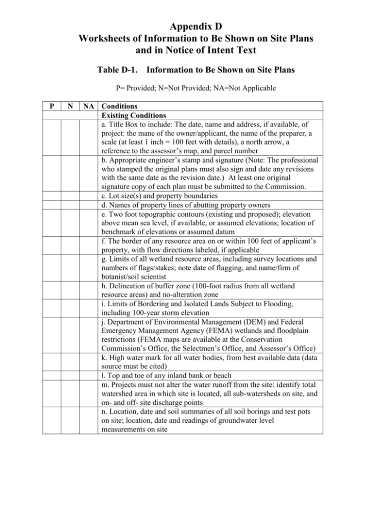
Appendix D Worksheets of Information to Be Shown on Site Plans and in Notice of Intent Text Table D-1. Information to Be Shown on Site Plans P= Provided; N=Not Provided; NA=Not Applicable P N NA Conditions Existing Conditions a. Title Box to include: The date, name and address, if available, of project: the mane of the owner/applicant, the name of the preparer, a scale (at least 1 inch = 100 feet with details), a north arrow, a reference to the assessor’s map, and parcel number b. Appropriate engineer’s stamp and signature (Note: The professional who stamped the original plans must also sign and date any revisions with the same date as the revision date.) At least one original signature copy of each plan must be submitted to the Commission. c. Lot size(s) and property boundaries d. Names of property lines of abutting property owners e. Two foot topographic contours (existing and proposed); elevation above mean sea level, if available, or assumed elevations; location of benchmark of elevations or assumed datum f. The border of any resource area on or within 100 feet of applicant’s property, with flow directions labeled, if applicable g. Limits of all wetland resource areas, including survey locations and numbers of flags/stakes; note date of flagging, and name/firm of botanist/soil scientist h. Delineation of buffer zone (100-foot radius from all wetland resource areas) and no-alteration zone i. Limits of Bordering and Isolated Lands Subject to Flooding, including 100-year storm elevation j. Department of Environmental Management (DEM) and Federal Emergency Management Agency (FEMA) wetlands and floodplain restrictions (FEMA maps are available at the Conservation Commission’s Office, the Selectmen’s Office, and Assessor’s Office) k. High water mark for all water bodies, from best available data (data source must be cited) l. Top and toe of any inland bank or beach m. Projects must not alter the water runoff from the site: identify total watershed area in which site is located, all sub-watersheds on site, and on- and off- site discharge points n. Location, date and soil summaries of all soil borings and test pots on site; location, date and readings of groundwater level measurements on site P= Provided; N=Not Provided; NA=Not Applicable P N NA Conditions, Continued o. Stone walls or other barriers located between the area of work and the area subject to protection under these regulations p. Locations and types of easements on site and on other properties within 50 feet of property line Proposed Conditions a. Work limits and location of temporary erosion controls; delineate areas where vegetation will be altered b. Proposed contours and amount of fill required to be added or removed (in cubic yards and maximum thickness); pre- and post development grades on all slopes 4 to 1 or steeper; locations of stockpiles c. Construction details, including cross-section and elevations, of drainage structures (including but not limited to catch basins, leaching basins, dry wells, swales, retention areas, ditches, etc.) and road crossings in wetland resource areas d. Equipment access routes and storage/parking area during proposed work e. All above-ground structures, roadways, access ways, stone walls, fences, and other physical alterations proposed; identify roadway or surface material proposed; location and elevation of lowest floor of all structures f. Existing natural drainage patterns and proposed alterations g. All below-ground alterations and structures, including but not limited to utility lines, drainage structures, on-site septic systems, cesspools, wells and storage tanks h. Location, capacity, and design details of on-site septic system i. Distance of proposed on-site leaching facility to wetlands, watercourses, or other resource areas j. For new construction, location of leaching facilities on other properties within 50 feet of the lot line, or 300 feet of the proposed project k. For new construction, location of all existing and proposed wells on property and within 200 feet of project on abutting properties, and minimum distance to all septic systems Table D-2. Information to Be Shown in Notice of Intent Text P= Provided; N=Not Provided; NA=Not Applicable P N NA Conditions Existing Conditions Topography, soils, and geology description Description of vegetation types, such as upland or wetland community types and plant species list Other relevant information Section of a U.S.G.S. quadrangle map, with site location circled (i.e. a locus map) Proposed Conditions Description of activities, construction sequencing and estimated timetable. Include description of future phases Description of indirect and direct impacts, both temporary and permanent, on wetland resource areas Description of soil erosion, sediment control plan, and mitigation plans for impacts for resource areas Details of mitigation plans for activities in the buffer zone to limit long term indirect impacts for adjacent resource areas Description of storm water management plan, including existing and proposed drainage areas Description of wastewater management plan Hydrologic calculations will conform to Soil Conservation Services procedures Wetlands creation/restoration plan, including area, with existing and proposed topography at contours at 1-foot intervals, and plans showing proposed grading, stockpiling, planting (indicate source of plants), and timetable Volume of fill required and source of fill Table D-3. Marking and Flagging Required Before Field Inspection P= Provided; N=Not Provided; NA=Not Applicable P N NA Marking and Flagging Edges of wetlands must be flagged with numbered flags, as reflected on submitted maps House number must be visible if it is an existing house; if no house is on property, the lot number must be posted and visible from the street Property boundaries must be staked at all corners All proposed structures or additions, including decks, must be staked for identification purposes at all corners; stakes must be numbered and labeled Septic tank, leaching field, and well locations must be staked with labeled stakes if within the buffer zone
