Notes by Anita Kanavalli MSRIT
advertisement
CHAPTER 3:THE TRANSPORT LAYER
Internet Protocols
• Internet transport services:
• reliable, in-order unicast delivery (TCP)
congestion
flow control
connection setup
• unreliable (“best-effort”), unordered unicast or multicast delivery: UDP
services not available:
real-time
bandwidth guarantees
reliable multicast
UDP
• “no frills,” “bare bones” Internet transport protocol
• “best effort” service, UDP segments may be:
– lost
– delivered out of order to applications
• connectionless:
– no handshaking between UDP sender, receiver
– each UDP segment handled independently of others
Why is there a UDP?
• no connection establishment (which can add delay)
• simple: no connection state at sender, receiver
• small segment header
• no congestion control: UDP can blast away as fast as desired
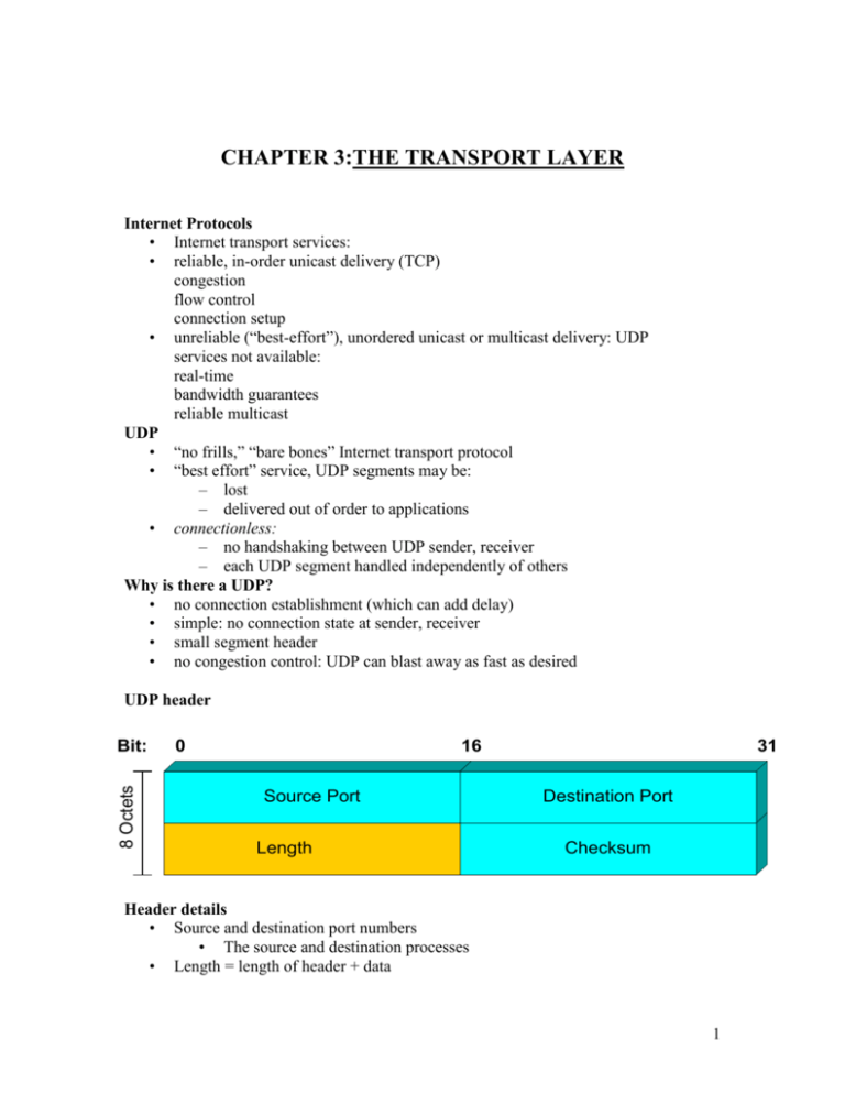
UDP header
8 Octets
Bit:
0
16
Source Port
Length
31
Destination Port
Checksum
Header details
• Source and destination port numbers
• The source and destination processes
• Length = length of header + data
1
•
Checksum covers header and data
• Optional in UDP but mandatory in TCP
UDP Checksum
Sender:
• treat segment contents as sequence of 16-bit integers
• checksum: addition (1’s complement sum) of segment contents
• sender puts checksum value into UDP checksum field
Receiver:
• compute checksum of received segment
• check if computed checksum equals checksum field value:
– NO - error detected
– YES - no error detected
Uses of UDP
•
Inward and Outward data collection/dissemination
– SNMP for network management
– RIP routing table updates
– NFS remote file server
• Request-Response
– Eg. DNS uses UDP for name translation
• Real time application
– Streaming multimedia and internet telephony
– Video conferencing
The following are the port numbers of some applications commonly used
•
•
•
•
Both TCP and UDP use port (or socket) numbers to pass information to the upper
layers.
Port numbers are used to keep track of different conversations that cross the
network at the same time.
Application software developers have agreed to use the well-known port numbers
that are defined in RFC1700.
The range of numbers are below 255 for TCP and UDP appilcations.
Applications of UDP
2
Remote Procedure Call
Mechanisms
• Client process calls the client stub
• Marshalling-packing the parameters
• Kernel receives from client stub and sends to server machine
• Kernel on server OS passes the message to server stub
• The server stub processes it and the reply follows the same path in the other
direction
Problems may occur in RPC
• Passing pointer parameters from client place to server space
• weakly typed language- C may not be suitable
• Type conversion
• Use of global variables –since two different space involved
Still UDP is commonly used in RPC
Another application of UDP a protocol uses UDP
3
(a) The position of RTP in the protocol stack.
(b) Packet nesting.
RTP Real time transport protocol
• UDP is used with real time multimedia applications
• the applications are: internet radio, internet telephony, music on demand, video
on demand, video conferencing
• RTP is used for different formats like GSM, MP3 for sound and MPEG and
H.263 for video
• The basic function of RTP is to multiplex several real time data stream onto
single stream of UDP packets. The UDP stream can be sent to single destination
(unicast) and multiple destination (multicast)
RTP Header details
• P padded bit
• X extension header present or not
• CC contributing sources
• M marker bit
• Version field
• Payload type
• Seq no
• Time stamp
• Synchronization and contributing source identifier
RTP Header
4
----------------------------------------------------------------------------------------------------
Transport Protocol TCP
socket
door
application
writes data
application
reads data
TCP
send buffer
TCP
receive buffer
socket
door
segment
Specially designed to provide a reliable end to end byte stream over a unreliable network
The inter network differs from a single network in terms of topology and bandwidth
delay packet size. TCP adapts to properties of such network. Each machine supporting
TCP has TCP entity. IP layer provide no guarantee that the datagrams will be delivered
so the TCP has to provide the reliability
TCP
• point-to-point:
– one sender, one receiver
• reliable, in-order byte steam:
– no “message boundaries”
• pipelined:
– TCP congestion and flow control set window size at the time of
connection setup
• send & receive buffers the buffer size negotiated
5
•
•
•
full duplex data:
– bi-directional data flow in same connection
– MSS: maximum segment size
connection-oriented:
– handshaking (exchange of control msgs) init’s sender, receiver state before
data exchange
flow controlled:
– sender will not overwhelm receiver
TCP Header
TCP segment structure
Seq. numbers:
– byte stream “number” of first byte in segment’s data
ACKs:
– seq numbers of next byte expected from other side
– cumulative ACK
Q: how receiver handles out-of-order segments
– A: TCP spec doesn’t say, - up to implementor
Every segment of TCP has a sequence number so it is easy to reassemble and also take
care of the loss of packet and retransmission is done
The segment details are shown below
6
The SYN bit used for connection setup and the FIN bit for the release
Urgent data means it has to be delivered faster which indicate by the pointer
The Checksum uses CRC
URG: urgent data
(generally not used)
ACK: ACK #
valid
PSH: push data now
(generally not used)
RST, SYN, FIN:
connection estab
(setup, teardown
commands)
32 bits
source port
dest port #
#
sequence
number
acknowledgement number
head not
UA P R S F
len used
checksum
Internet
checksum
(as in UDP)
rcvr window size
ptr urgent data
Options (variable
length)
counting
by bytes
of data
(not segments!)
# bytes
rcvr willing
to accept
application
data
(variable length)
TCP connection establishment
TCP sender, receiver establish “connection” before exchanging data segments
• initialize TCP variables:
– seq. nubers
– buffers, flow control info (e.g. RcvWindow)
• client: connection initiator
Socket clientSocket = new Socket("hostname","port number");
• server: contacted by client
Socket connectionSocket = welcomeSocket.accept();
Three way handshake
Step 1: client end system sends TCP SYN control segment to server
– specifies initial seq number
Step 2: server end system receives SYN, replies with SYNACK control segment
7
– ACKs received SYN
– allocates buffers
– specifies server-> receiver initial seq. number
Step 3: client sends the request and the ack for the server seq number
The three way handshake is over
Connection Release
client closes socket: clientSocket.close();
Step 1: client end system sends TCP FIN control segment to server
Step 2: server receives FIN, replies with ACK. Closes connection, sends FIN
Step 3: client receives FIN, replies with ACK.
– Enters “timed wait” - will respond with ACK to received FINs
Step 4: server, receives ACK. Connection closed.
Note: with small modification, can handle simultaneous FINs.
The connection management client side can be shown in a flow diagram
The connection management server side can be shown in a flow diagram
8
Connection management
The two figures
(a) TCP connection establishment in the normal case.
(b) Call collision.
The states used in the TCP connection management finite state machine.
9
10
•
•
•
•
•
TCP connection management finite state machine.
The heavy solid line is the normal path for a client.
The heavy dashed line is the normal path for a server.
The light lines are unusual events.
Each transition is labeled by the event causing it and the action resulting from it,
separated by a slash.
---------------------------------------------------------------------------------------------------------
11
TCP connection management
•
•
•
•
•
•
•
•
Server waits by executing LISTEN and ACCEPT primtives
Client executes a CONNECT primitive specifying IP and PORT no, max TCP
segment size and user data
CONNECT sends TCP segment with SYN bit ON and ACK off
Server can either accept or reject connection
In call collision only one connection is established
Connection released using FIN bit
One FIN and one ACK in each direction
possible to combine first ACK and second FIN in the same segment
Finite state machine
• Management on client side
• When client issue CONNECT, TCP entity sends SYN segment
• Separate state for each connection
• When ACK arrives the final ACK sent and switches to new state
• Data transfer
• when no data issue CLOSE primitive sends FIN segment
• One side goes to WAIT and waits for the FIN from other side
• Packet life time taken care too
• Management on server side
• When server issue LISTEN and waits for incoming request
• When SYN comes the server responds with ACK
• When three way handshake complete then server goes to new state
• FIN is sent when server want to close
TCP transmission policy
•
•
•
•
•
•
Sender & receiver negotiate on window size
In the figure below the sender sends 2K data and the initial seq no
The receiver sends the ack for the next seq no it is expecting and also advertises
the widow size
Suppose the window is zero then sender waits and then sends a probe and then
sends the next set of data
The diagram shows how the two sides communicate
Suppose there is only one byte to be sent the 41 byte packet to be sent instead
Nagle algorithm suggest that when the first byte comes it is sent and the other
buffered till the ack received and then send the rest and wait for the ack and like
this a sufficient no of bytes go in one segment
12
Silly window syndrome
At the receiver side even if a byte available at its buffer it advertised and the sender sends
the buffer is full the sender waits again and probes to get the window size so this will
continue and a loop formed to avoid this the receiver is forced to wait till good amount of
buffer space availability and then advertises and avoids the loop.
TCP Congestion control
13
Congestion:
• informally: “too many sources sending too much data too fast for network to
handle”
• different from flow control!
• manifestations:
– lost packets (buffer overflow at routers)
– long delays (queueing in router buffers)
Problems when congestion happens
•
•
•
two senders, two
receivers
one router, infinite
buffers
no retransmission
•
•
large delays
when congested
maximum
achievable
throughput
14
•
•
one router, finite buffers
sender retransmission of lost packet
•
•
•
four senders
multihop paths
Q: what happens inas
andin increase ?
timeout/retransmit
15
Another “cost” of congestion:
•
when packet dropped, any “upstream transmission
capacity used for that packet was wasted!
16
TCP Congestion control
• How TCP prevents congestion
• when connection established, window size chosen
• Receiver specifies seeing its buffer size
• Still congestion occurs
• The two problems are Network Capacity and Receiver Capacity
• Solution?
• Solution
• Sender maintains two windows: one the receiver granted
• the other Congestion Window
• at the connection establishment- the congestion window is set to the size of the
maximum segment in use on the connection
• Each burst acknowledged doubles the congestion window
• Congestion window grow exponentially
• This is called the Slow Start algorithm
• Another Solution?
Host A
Host B
Slowstart algorithm
initialize: Congwin = 1
for (each segment ACKed)
Congwin++
until (loss event OR
CongWin > threshold)
RTT
one segment
two segments
four segments
time
•
•
•
•
•
•
Solution
Uses threshold
initially some value in addition to the receiver and congestion window
When timeout threshold is set to half of the current congestion window
Congestion window is set to one max segment
Slow start is used to find what the network can handle
17
•
•
Exponential growth stops when threshold hit
From that point congestion window grow linearly
Congestion avoidance
/* slowstart is over
*/
/* Congwin > threshold */
Until (loss event) {
every w segments ACKed:
Congwin++
}
threshold = Congwin/2
Congwin = 1
perform slowstart 1
•
•
•
•
•
•
Example
Segment size=1K
Congwin=64KB
when timeout threshold=34KB
Congwin=1KB
the congstion window grows exponentially until it hits threshold and then linearly
TCP timer management
Round trip time RTT
how to set TCP timeout value?
• longer than RTT
– note: RTT will vary
• too short: premature timeout
– unnecessary retransmissions
• too long: slow reaction to segment loss
• The algorithm is based on continuous measurements of network performance
• Jacobson algorithm is one used for calculating RTT
• For each connection a value RTT is maintained
• RTT updated using the formula
• RTT=αRTT+(1- α)M
• Where M is time taken for ACK
• And α is the smoothing factor
• And α=7/8
TCP RTT
18
•
•
•
•
•
•
•
•
Jacobson algorithm
Another smoothed value D deviation it is the difference between the expected
and observed value |RTT-M|
D= α D+(1- α )|RTT-M|
Timeout interval =RTT+4*D
The problem with retransmission answered by Karn’s algorithm
RTT not updated for retransmitted segment timeout is doubled on each failure till
the segment gets through first time
There is another timer called the persistence timer- it is used when the sender is
made to wait due to lack of buffer space at the receiver. Once this timer goes off
the sender sends the probe to find about the receiver buffer space otherwise a
deadlock occurs so this timer is used to resolve the same
The third timer is the keepalive timer- it is used for the connections which are
idle for a long time suppose this timer goes off then the connection is closed
Wireless TCP
•
•
•
•
•
Indirect TCP to split the TCP connection into two separate connections
first one from sender to base station the second from base station to receiver
the advantage is both connections are homogeneous
The disadvantage is that it breaks the semantics of TCP
There is another solution for keeping the semantics of TCP is the Transactional
TCP
Transactional TCP
19
The above figure (a) shows the normal RPC call where nine messages are exchanged
between the client and the server
Figure (b) shows the one with Transactional TCP T/TCP where request and SYN and
also FIN are sent together thus reducing the messages and providing faster service
--------------------------------------------------------------------------------------------------
20
Different performance issues in network
•
•
•
•
•
Performance Problems in Computer Networks
Network Performance Measurement
System Design for Better Performance
Fast TPDU Processing
Protocols for Gigabit Networks
Performance problems in computer networks
• Overloads Example 1: TPDU containing the bad parameter when broadcast may
clog the n/w results in broadcast storm due to error message
• synchronous overload due to power failure-DHCP contacted for booting
• Apart from this problems due to insufficient memory TPDUs lost
• Not setting the timeout correctly the TPDUs lost
• Gigabit n/w pose new problems
• The next figure explains this here the transmission line used only for .5msec
greatly reducing the efficiency
•
•
•
•
•
The useful quantity is the Bandwidth-Delay product
The product is the capacity of the pipe from sender to receiver and back to sender
in bits
In the above example it is 40 million bits but the actual utilisation is only 1.25
percent of the pipe capacity
therefore for good performance the receiver window must be at least as large as
the Bandwidth-Delay product
Another performance problem could be jitter to avoid a small standard deviation
is used
21
The basic loop for improving network performance.
• Measure relevant network parameters, performance.
• Try to understand what is going on.
• Change one parameter
Precautions taken while measuring
•
•
•
•
•
•
•
Sample size should be large enough
Samples should be representative
To be careful while using coarse grained clock
Nothing unexpected going on while tests are conducted
Caching problem
Understanding the measurements
Extrapolation of the result
System Design for Better Performance
Rules:
• CPU speed is more important than network speed.
• Reduce packet count to reduce software overhead.
• Minimize context switches.
• Minimize copying.
• You can buy more bandwidth but not lower delay.
• Avoiding congestion is better than recovering from it.
• Avoid timeouts.
Fast TPDU Processing
•
•
•
•
•
•
TPDU processing overhead has two components
one –overhead per TPDU
other – overhead per byte
Example take the sending side
first the sending side traps to kernel to SEND
if it is a normal case then the state is ESTABLISHED and typically this path is
taken (fast path) shown in the figure below
22
The fast path from sender to receiver is shown with a heavy line.
The processing steps on this path are shaded.
Another example
• In the TCP header the fields that are same between consecutive TPDUs on a one
way flow are shaded
• All sending TCP entity has to copy from the prototype header into the output
buffer
• It handovers the header and data to the special IP procedure for sending a regular
max TPDU
• IP then copies its prototype header and makes the packet ready
the above figure
(a) TCP header. (b) IP header. In both cases, the shaded fields are taken from the
prototype without change.
Fast path processing at receiver side
• step 1: locating the connection record for the incoming TPDU
• The TPDU checked to see if it is normal case
• If all checks are met then a fast procedure is called
• Many TCP implementations use Header Prediction
23
•
•
•
•
The other two areas where major performance gain are possible are
Buffer management
Timer Management
The timer management done by the timing wheel
There are some problems and the possible solution posed by the Gigabit protocols
Problems
Sequence Numbers
Communication Speeds
Go back n protocol and its poor performance
gigabit lines are bandwidth limited
Results of new application
------------------------------------------------------------------------------------------------------------
24
1: Define the following terms:
(a) Slow start
Answer
The phase in TCP congestion control when the window size starts at one segment and
increases by one segment for every ACK received (that is, it sends first one segment, the
two, the four, then eight, and so on, as ACKs arrive for the segments transmitted.
(b) Three-way handshake
Answer
The mechanism used to set up a connection and agree upon the initial sequence numbers
for that connection. In the normal case, host 1 will send a connection requestion and
sequence number to host 2. Host 2 will acknowledge the request, and make a
corresponding request to host 1 with its own choice of sequence number. Host 1 will
acknowledge the request from host 2. The connection is now established.
2: What is the difference between
flow control and congestion control?
Answer
Flow control prevents a fast sender from overwhelming a slow receiver.
Congestion control prevents many senders from overwhelming the network.
3: When doing a connection setup in TCP both parties are required to pick a random
number for the initial sequence number.
(a) Ignoring security concerns, why do they not just pick 0 or 1?
Answer
This would substantially increase the likelihood of a “lost” segment from a previous
connection re-appearing and messging up an existing connection.
(b) Why do they not just increment the last used sequence number for the particular
source/destination pair (assuming that we could readily keep track of this information)?
Answer
It allows a third party to fake a connection.
4: When TCP receives a segment that it has already received and acknowledged, it will
reply with an acknowledgement.
(a) Why is this acknowledgment necessary?
Answer
The previous acknowledgement may have been lost.
5:The sequence number of the segment received is 1234, and the length of the segment is
10 bytes.
(a) Do we know what the acknowledgement number will be that TCP will reply with?
If so, what is it? If not, why not? What can we say about the acknowledgement number
that TCP will reply with?
25
5:Answer
No. We do not. If this is the greatest contiguous segment currently received, then the
ACK will be 1244. However, if a prior segment has been lost, then the acknowledgement
number will be less than 1234. Likewise, if this is a retransmission of segment 1234, and
a subsequent segment has been received, the acknowledgement may be greater than 1244.
We do know that it will be either less than 1234 or greater than or equal to 1244.
6: If TCP retransmits a segment, what impact, if any, does this have on the RTT
calculation?
Answer
This transmission/retransmission cannot be included in the estimate, as we cannot
distinguish where the acknowledgement came from: the first segment, and it was delayed,
or the second segment.
7: Why does TCP require an RTT estimate?
Answer
To determine if a segment has been lost or not. A segment is deemed lost if the ACK for
it is not received within the timeout period which is derived from that RTT.
8: A network has a maximum packet size of 128 bytes, a maximum packet life time as 10
sec and a 8bit sequence number. Find the maximum data rate per connection
Answer
Given 8 bit sequence numbers 2(pow)8=256 packets sent in 10 sec
In 10 sec 128*8*255=261120 bits can be sent
Max data rate per connection=261120/10 seconds
=26112 bits/sec
9: A TCP machine is sending full windows 65535 bytes over a 1Gbps channel that has a
10msec delay one way. What is the maximum throughput achievable? What is the line
efficiency?
Answer
Given RTT=10+10=20msec=1/20*10(pow)-3
= 50bits/sec
Max throughput=(65535*8)bits*50bits/sec
=26.214Mbps
Line efficiency=Max throughput/Bandwidth
= (26.214Mbps/1Gbps)*100 = 2.62%
10: What is meant by upward and downward multiplexing?
Answer
In upward the multiple connections are multiplexed on to a single connection
In downward a single connection is split and distributed among multiple connection
11: Describe congestion control in TCP
Answer
26
Slow start
12: Explain UDP. When it can be used?
Answer
Connectionless unreliable internet protocol
Applications
RPC
Real time applications
13:What is meant by nesting of TPDUs? Illustrate with the diagram the connection
establishment between a client and a server using TPDUs
14: Illustrate the silly window syndrome in TCP
-----------------------------------------------------------------------------------------------------
27
28
