The Lens Equation Exercise 8 The Lens Equation 8.1. Introduction
advertisement

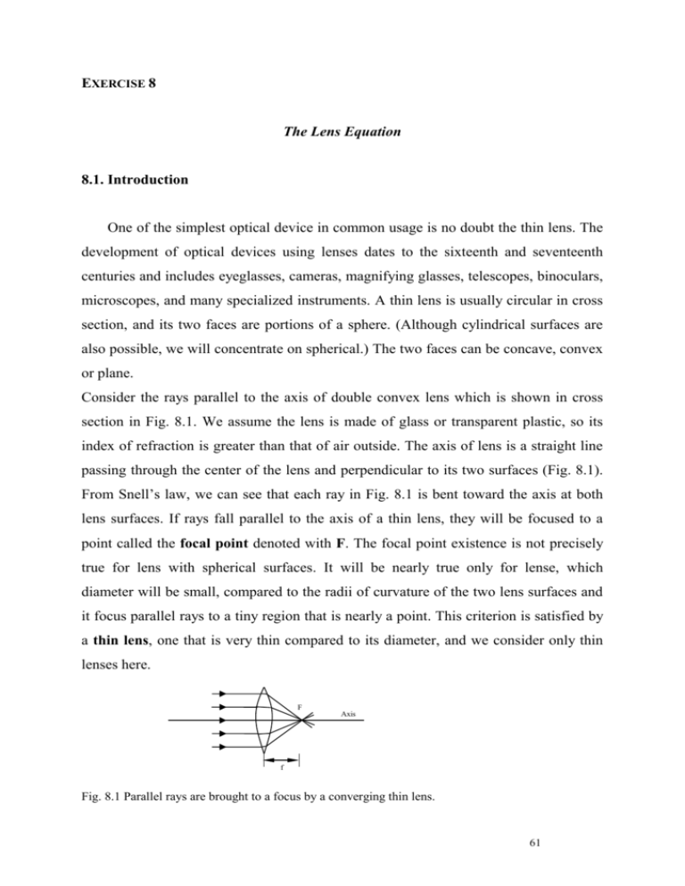
EXERCISE 8 The Lens Equation 8.1. Introduction One of the simplest optical device in common usage is no doubt the thin lens. The development of optical devices using lenses dates to the sixteenth and seventeenth centuries and includes eyeglasses, cameras, magnifying glasses, telescopes, binoculars, microscopes, and many specialized instruments. A thin lens is usually circular in cross section, and its two faces are portions of a sphere. (Although cylindrical surfaces are also possible, we will concentrate on spherical.) The two faces can be concave, convex or plane. Consider the rays parallel to the axis of double convex lens which is shown in cross section in Fig. 8.1. We assume the lens is made of glass or transparent plastic, so its index of refraction is greater than that of air outside. The axis of lens is a straight line passing through the center of the lens and perpendicular to its two surfaces (Fig. 8.1). From Snell’s law, we can see that each ray in Fig. 8.1 is bent toward the axis at both lens surfaces. If rays fall parallel to the axis of a thin lens, they will be focused to a point called the focal point denoted with F. The focal point existence is not precisely true for lens with spherical surfaces. It will be nearly true only for lense, which diameter will be small, compared to the radii of curvature of the two lens surfaces and it focus parallel rays to a tiny region that is nearly a point. This criterion is satisfied by a thin lens, one that is very thin compared to its diameter, and we consider only thin lenses here. F Axis f Fig. 8.1 Parallel rays are brought to a focus by a converging thin lens. 61 THE LENS EQUATION The most important parameter of a lens is a focal length f. Once f is known, the image position can be found for any given object. Finding the image point by drawing rays would be difficult if we would have to determine all the refractive angles. Instead, we can do it in a simpler manner by making use of a certain facts we already know, such as that a ray parallel to the axis of the lens passes (after refraction) through the focal point. In fact, to find an image point, we need consider only three rays indicated in Fig. 8.2, which shows an arrow as the object and a converging lens forming an image to the right. Object 1 1 F’ F Object (a) Ray 1 1 1 F’ Image F 2 (b) Ray 2 2 Object 1 3 1 F’ Image F 2 (c) Ray 3 2 Fig.8.2 Finding the image by ray tracing for a converging lens. Rays leave each point on the object. The three most useful rays are shown , leaving the tip of the object, for determining where the image of that point is formed. These rays, emanating from a single point on the object, are drawn as if the lens were infinitely thin, and we show only a single sharp bend within the lens instead of the refractions at each surface. These three rays are drawn as follows: 62 THE LENS EQUATION Ray 1 is drawn parallel to the axis; therefore it is refracted by the lens so that it passes along a line through the focal point F, (Fig. 8.2.a). Ray 2 is drawn on a line passing through the other focal point F’ (front side of lens in Fig. 2) and emerges from the lens parallel to the axis, (Fig. 8.2.b). Ray 3 is directed toward the center of the lens, where the two surfaces are essentially parallel to each other; this ray therefore passes through the lens without bending; the ray would be displaced slightly to one side, but since we assume the lens is thin, we draw ray 3 straight through as shown (Fig. 8.2.c). Actually, any two of these rays will suffice to locate the image point, which is the point where they intersect. Drawing the third can serve as a check. In this way we can find the image point for one point of the object (the top of arrow in Fig. 8.2). The image points on the object can be found similarly to determine the complete image of the object. Because the rays actually pass through the image for the case shown in Fig. 8.2, it is a real image. Now, we can derive an equation that relates the image distance to the object distance and the focal length of the lens. This will make the determination of image position quicker and more accurate than doing ray tracing. Let d0 be the distance of the object from the center of the lens, and di be the distance of the image from the center of the lens; let also h0 and hi refer to the heights of the object and image. O’ B ho F O F’ I A hi I’ f do di Fig. 8.3 Deriving the lens equation for a converging lense. 63 THE LENS EQUATION Consider the two rays shown in Fig. 8.3 for a converging lens (assumed to be very thin). The triangles FI’I and FBA (Fig. 8.3) are similar because angle AFB equals angle IFI’; so hi d i f h0 f (8.1) since length AB=h0. Triangles OAO’ and IAI’ are similar. Therefore, hi d i h0 d 0 (8.2) We equate the right sides of these two equations, divide by di, and rearrange to obtain 1 1 1 d0 di f (8.3) This is called the lens equation. It relates the image distance di to the object distance d0 and the focal length f. It is the most useful equation in geometric optics. The lateral magnification m, of a lens is defined as the ratio of image height to object height, m=hi/h0. Thus according to the conventions stated in Fig. 8.3 we have m hi d i h0 d0 (8.4) 8.2. Measurements do So di f Crossed arrow target f Si lens Viewing screen Fig. 8.4.Experimental setup. 64 THE LENS EQUATION Set up the equipment as shown in Fig. 8.4. Turn on the Light Source and slide the lens toward or away from the Crossed Arrow Target, to focus the image of the Target onto the Viewing Screen. Now set d0 to the values (in milimeters) listed in the table below. At each setting, locate the image and measure di. Also measure hi, the height of image (h0 is the height of the arrow on the crossed arrow target). Measurements should be repeated 6 times. Using the data you have collected, perform the calculations shown in the table 8.1. Are your results in complete agreement with the Fundamental Lens Equation? If not, what is the source of the discrepancies? 8.3. Results, calculation and uncertainty The data should be collected in a table 8.1. Table 8.1 Data d0 [mm] di [mm] Calculations hi [mm] 1/di + 1/d0 f [mm] hi/h0 -di/d0 500 450 400 350 300 250 200 150 100 75 50 65 THE LENS EQUATION Calculate the focal length of the lens and lateral magnification using eq. 8.1, 8.3 and 8.4. Estimate the uncertainty of the measured values by calculating the standard deviation. The final results read: f f Sf (8.5) m m Sm (8.6) 8.4. Questions 1. Based on the Fundamental Lens Equation, explain what would happen to di if you increased d0 even further? What would happened to di if d0 were very, very large? 2. What value of d0 will make you unable to focus an image onto the screen? Use the Fudamental Lens Equation to explain why. 3. What kind of Fundamental Lens Equation do you know? 4. What kind of parameters decide about the kind of obtained image? 5. What kind of image can you observe in a microscope, cinema and in the human eye? Explain it using the Fundamental Lens Equation. 6. What types of lenses do you know ? 7. What happens to the image as you change the distance between an object and lens. 8. What is an aberration ? 9. Explain vision correction by glasses. 10. Derive law of refraction from Fermat’s principle. 8.5. References 1. Dryński T., Ćwiczenia laboratoryjne z fizyki, PWN, Warszawa, 1959 2. Resnick R., Halliday D., Fizyka, Tom 2, PWN, Warszawa, 1989 3. Szydłowski H., Pracownia fizyczna, PWN, Warszawa, 1994 4. Young H.D., Freedman R.A., University Physics with Modern Physics, Addison-Wesley Publishing Company, 2000 66


