Designing Model Exchange Processes paper
advertisement
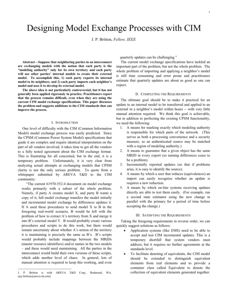
1 Designing Model Exchange Processes with CIM J. P. Britton, Fellow, IEEE Abstract—Suppose that neighboring parties in an interconnect are exchanging models with the notion that each party is the “modeling authority” only for its own territory and each party will use other parties’ internal models to create their external model. To accomplish this, 1) each party exports its internal model to its neighbors, and 2) each party imports each neighbor’s model and uses it to develop its external model. The above idea is not particularly controversial, but it has not generally been applied rigorously in practice. Practitioners report that the process remains difficult, even when they are using the current CIM model exchange specifications. This paper discusses the problem and suggests additions to the CIM standards that can improve the process. I. INTRODUCTION One level of difficulty with the CIM (Common Information Model) model exchange process was easily predicted. Since the CPSM (Common Power System Model) specifications that guide it are complex and require identical interpretation on the part of all vendors involved, it takes time to get all the vendors to a fully tested agreement about the CIM exchange format. This is frustrating for all concerned, but in the end, it is a temporary problem. Unfortunately, it is very clear from analyzing actual attempts at exchanging models that CPSM clarity is not the only serious problem. To quote from a whitepaper submitted by AREVA T&D to the CIM community: “The current 61970-552-4 document on model exchange works primarily with a subset of the whole problem. Namely, if party A creates model X, and party B wants a copy of it, full model exchange transfers the model initially and incremental model exchange by differences updates it. If A used these procedures to send model X to B in the foregoing real-world scenario, B would be left with the problem of how to extract A’s territory from X and merge it into B’s external model Y. B would probably create various procedures and scripts to do this work, but there would remain uncertainty about whether A’s notion of the territory it is maintaining is precisely the same as B’s. B’s scripts would probably include mappings between the MRIDs (master resource identifiers) and/or names in the two models – and these would need maintaining. All the parties in the interconnect would build their own versions of these scripts, which adds another level of chaos. In general, lots of manual attention is required to keep this working, and even J. P. Britton is with (jay.britton@areva-td.com) AREVA T&D Corp., Redmond, WA. quarterly updates can be challenging.” The current model exchange specifications have tackled an important part of the problem, but not the whole problem. The whole problem of importing and applying a neighbor’s model is still time consuming and error prone and practitioners estimate that quarterly updates are about as good as one can expect. II. COMPLETING THE REQUIREMENTS The ultimate goal should be to make it practical for an update to an internal model to be transferred and applied to an external in a neighbor’s model within hours -- with very little manual attention required. We think this goal is achievable, but in addition to perfecting the existing CPSM functionality, we need the following: 1. A means for marking exactly which modeling authority is responsible for which parts of the network. (This serves as both a processing convenience and a security measure, so an authenticated source may be matched with a region of modeling authority.) 2. A means to guarantee that a given object has the same MRID in every export (so naming differences cease to be a problem). 3. Incrementally reported updates (so that if problems arise, it is easy to identify the source). 4. A means by which a user that reduces (equivalences) an import can easily recognize whether an update is requires a new reduction. 5. A means by which on-line systems receiving updates directly are able to test them easily. (For example, run a second state estimator using the new change in parallel with the primary for a period of time before accepting the change.) III. SATISFYING THE REQUIREMENTS Taking the foregoing requirements in reverse order, we can quickly suggest solutions as follows: Application systems (like EMS) need to be able to accept and test CIM incremental updates. This is a temporary shortfall that system vendors must address, but it requires no further agreements at the standards level. To facilitate denoting of equivalents, the CIM model should be extended to distinguish equivalent elements from real elements and to provide a container class called Equivalent to denote the collection of equivalent elements generated together. 2 A-C boundary primarily using well known control area tie points. Boundary sets will be small and consist primarily of the Connectivity Node objects at the tie points, which is illustrated in Fig. 2. Since boundary sets are small, they rarely have to be changed. The vast majority of changes may be made unilaterally by a region authority acting on its own RMA set. Such changes may be validated against the boundary sets without checking against other regions. A Region C Region A-B boundary B-C boundary (Note, however, that individual receivers could also invent their own mechanisms here, because it would not disturb the exchange process if different parties denoted equivalents in different ways.) A business agreement needs to be made about reporting changes incrementally and regularly, but incremental updates are already defined and no further standard is required. CPSM presently does not require that MRIDs be consistent from one export to another, but this is easily added and any system for achieving this end may be adopted by a given exporter. This brings us to the final question of specifying modeling authority, which must be a mutual agreement and is just a little more difficult. How do A and B define their boundary clearly? How does party A know in general whether deleting an object in A’s territory might break a reference from an object in party B’s turf? How does a receiver of an update that added new elements check whether the source was the modeling authority? The proposed solution is to divide the model into disjoint regional model authority (RMA) sets of objects, in which there are two types of RMA sets: Regional sets contain no objects that reference objects in another regional set. Boundary sets contain all objects that have relationships with objects in different regional sets. Consider a two-region example, where A, B, X are RMA sets, respectively representing region A, region B and the boundary set between them. These sets have the property that all relationship keys in A are satisfied within A u X and all relationship keys in B are satisfied within B u X. Per our requirements, we might also expect that region A defines a reduction script, rA(B), to generate A’s external model of B and likewise region B defines a reduction script, rB(A), to generate B’s external model of A. There are now three models of interest… A u X u B is the “full” interconnect detail. A u X u rA(B) is A’s operating model. B u X u rB(A) is B’s operating model. This basic arrangement extends to any number of regional authorities in an interconnect… The number of regional sets is equal to the number of regional authorities. The number of boundary sets is equal to the number of pairs of regions sharing ties. The number of interconnection models is n+1, where n is the number of regions. All models, however, are derived the same set of sources. A CIM model container class is proposed as the means to designate which objects belong to which set. Each object is in one and only one set, as illustrated for a three region example in Fig. 1. In practice, regional authority will be divided B Region Fig. 1. Three regional sets separated by three boundary sets. C Region Substation Tie Line Metering Point A Region Transmission Line A Regional Set T LN m A-C Boundary Set T CN C Regional Set CN T T T T CB CB CB CB T T T T M Fig. 2. Simplified view of objects and relationships at a boundary point between a line and substation. (T=Terminal; LN=Line; CN=Connectivity Node; CB=Circuit Breaker; M=Measurement) IV. BENEFITS OF THIS APPROACH A. Generality RMA sets provides a completely general way to organize shared responsibility for objects in a data model. The technique does not depend on, and is not limited to, any characteristics of the physical electrical system. This is important because although the electrical connection relationships are the most numerous single type of 3 relationship, there are many other relationships that could cause confusion, such as load modeling hierarchies, ownership relationships, voltage control relationships and the like. With RMA sets, the same approach works across all relationship and object types and will not be disturbed by any future evolutionary changes to CIM. B. Naming & MRIDs Much discussion has occurred around the problem of identifiers and management of different systems using different names for the same object. The CIM community currently is considering standardizing the characteristics of a name registry, but the most problematic aspect of such a registry is the business process that will guarantee that one and only one party registers a given object. Regional model authorities, delineated in RMA sets, make this problem much simpler. They clearly establish the authority for every object. In the RMA world, the only requirements for MRIDs are that they are globally unique and consistently used in each RMA exports. Basically, each regional model authority can issue MRIDs in its territory, and as long as each authority generates MRIDs such that they will never be duplicated by another authority, the authorities can operate independently of one another. There is no necessity to create a single registry. C. Processing Efficiency Since an entire model is a simple union of RMA sets, merge and replace operations by RMA set are simple and correspondingly efficient. With RMA sets, there is very little incentive to exchange whole models as one CIM model transfer. (Most operations would be updating one RMA set at a time anyway, and in those cases where someone does want an entire model at one time, shipping the model as individual sets is still practical because merging the result is straightforward.) This means that huge interconnects, like the Eastern Interconnect in North America, do not necessarily have to produce gargantuan XML files. If the interconnect is divided into RMA sets, then maximum XML file size is determined only by the largest region. D. Verification of Authority On a more subtle level, making it practical to update external models quickly will introduce the need to verify that updates are really being formed by the right parties. Putting aside any issue of diabolic intention, it would be quite easy, in the absence of protective mechanisms, for a modeler in region A to mistake where he or she was in the model and to generate a change that applied to someone else’s territory. RMA sets make it easy to determine if you are modifying something that you have the right to modify. First, all objects have an RMA designator. Second, any regional update can easily be verified for completeness given only the regional RMA set and its boundary RMA sets. Third, if a user finds in the course of creating a update that a change is needed in either a boundary or another region, then that is a clear indicator that the modeler cannot proceed individually and must communicate with other parties. RMA sets also make it easy as a receiver to check whether an update from a source is valid. If region A sends and update, then that update must be referentially complete within the region RMA set and its boundary sets. V. CONCLUSION RMA sets provide a straightforward and very general method for specifying collaborative modeling in an interconnected power system. In combination with further refinement of existing CIM model exchange standards, and with addition of facilities for testing incremental updates within using systems, they make it practical to achieve a vision in which each party can form and maintain models of their external system directly from the internal models of their neighbors. VI. REFERENCES Standards: [1] Draft IEC 61970: Energy Management System Application Programming Interface (EMS-API) – Part 301: Common Information Model, Revision 6, Feb., 2002. [2] Draft IEC 61970: Energy Management System Application Programming Interface (EMS-API) – Part 452: CIM Model Exchange Specification, Revision 0, Jan., 2004. [3] Draft IEC 61970: Energy Management System Application Programming Interface (EMS-API) – Part 552-4: CIM XML Model Exchange Format, Draft Revision 6, May, 2005. [4] CPSM Minimum Data Requirements in Terms of the IEC CIM, Revision 2.0, Feb., 2006. VII. BIOGRAPHIES Jay P. Britton (M’1968, F’1997) was born in DeKalb, IL, USA in 1945. He holds a BSE EE from Princeton University (1967). He is currently Principal Architect and Product Manager with AREVA T&D Corporation. Other work experience includes Commonwealth Edison Co, Systems Control Inc., ESCA Corp., KEMA Consulting, and Xtensible Solutions. Mr. Britton is a member of IEC WG13 and WG19, and the CIM User Group, and is deeply involved with the CIM standards. His past work spans such subtopics as network applications, power system modeling, application development tools, and systems architecture.
