doc version - Physics - Princeton University
advertisement

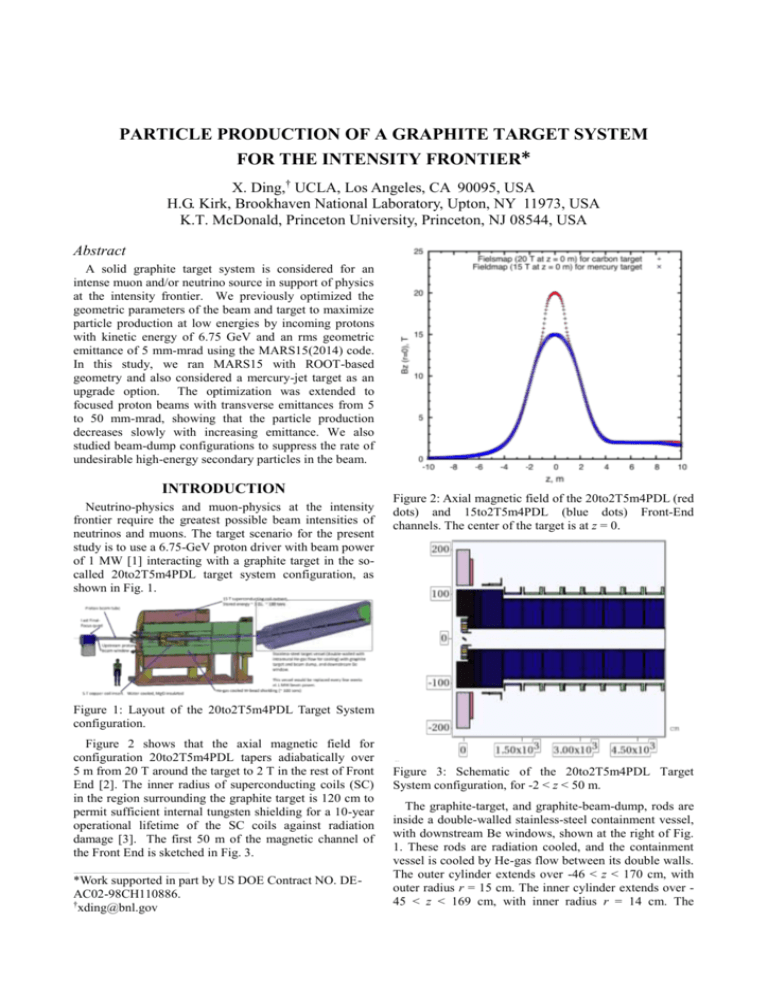
PARTICLE PRODUCTION OF A GRAPHITE TARGET SYSTEM FOR THE INTENSITY FRONTIER* X. Ding,† UCLA, Los Angeles, CA 90095, USA H.G. Kirk, Brookhaven National Laboratory, Upton, NY 11973, USA K.T. McDonald, Princeton University, Princeton, NJ 08544, USA Abstract A solid graphite target system is considered for an intense muon and/or neutrino source in support of physics at the intensity frontier. We previously optimized the geometric parameters of the beam and target to maximize particle production at low energies by incoming protons with kinetic energy of 6.75 GeV and an rms geometric emittance of 5 mm-mrad using the MARS15(2014) code. In this study, we ran MARS15 with ROOT-based geometry and also considered a mercury-jet target as an upgrade option. The optimization was extended to focused proton beams with transverse emittances from 5 to 50 mm-mrad, showing that the particle production decreases slowly with increasing emittance. We also studied beam-dump configurations to suppress the rate of undesirable high-energy secondary particles in the beam. INTRODUCTION Neutrino-physics and muon-physics at the intensity frontier require the greatest possible beam intensities of neutrinos and muons. The target scenario for the present study is to use a 6.75-GeV proton driver with beam power of 1 MW [1] interacting with a graphite target in the socalled 20to2T5m4PDL target system configuration, as shown in Fig. 1. Figure 2: Axial magnetic field of the 20to2T5m4PDL (red dots) and 15to2T5m4PDL (blue dots) Front-End channels. The center of the target is at z = 0. Figure 1: Layout of the 20to2T5m4PDL Target System configuration. Figure 2 shows that the axial magnetic field for configuration 20to2T5m4PDL tapers adiabatically over 5 m from 20 T around the target to 2 T in the rest of Front End [2]. The inner radius of superconducting coils (SC) in the region surrounding the graphite target is 120 cm to permit sufficient internal tungsten shielding for a 10-year operational lifetime of the SC coils against radiation damage [3]. The first 50 m of the magnetic channel of the Front End is sketched in Fig. 3. ____________________________________________ *Work supported in part by US DOE Contract NO. DEAC02-98CH110886. † xding@bnl.gov Figure 3: Schematic of the 20to2T5m4PDL Target System configuration, for -2 < z < 50 m. The graphite-target, and graphite-beam-dump, rods are inside a double-walled stainless-steel containment vessel, with downstream Be windows, shown at the right of Fig. 1. These rods are radiation cooled, and the containment vessel is cooled by He-gas flow between its double walls. The outer cylinder extends over -46 < z < 170 cm, with outer radius r = 15 cm. The inner cylinder extends over 45 < z < 169 cm, with inner radius r = 14 cm. The downstream faces of the vessels are Be windows, 1 mm thick. The Front End for 5 < z < 50 m consists of nine 5-mlong superconducting magnet modules, each with internal tungsten shielding around the 23-cm-radius beam pipe. The latter has thin Be windows, 0.05 mm thick, at each end of a magnet module, and is filled with He gas at 1 atmosphere. CARBON TARGET OPTIMIZATION The MARS15(2014) code [4] with its default setting for event generation (ICEM 4 = 1) were used for target optimization. The proton beam was launched at z = −100 cm so as to have a specified rms transverse emittance, beam angle and waist at the center of the target (z = 0), after propagating in the magnetic field. For this, an antiproton beam was generated at z = 0 with the specified parameters, propagated back to z = - 100 cm without a target, and then the charge and momentum was reversed, and the target restored, for subsequent propagation in the positive z direction. The pions and muons from the target of interest to a Muon Collider/Neutrino Factory are those with kinetic energies between 40 and 180 MeV. The optimization used here is based on maximizing the yield of these particles at the plane z = 50 m, which is near the beginning of the Buncher of the Front-End [2]. The graphite density was assumed to be 1.8 g/cm3. In a previous optimization [5] for incoming protons with kinetic energy of 6.75 GeV and rms geometric emittance of 5 mm-mrad, we found the optimized geometric parameters of the beam and target to be: target length = 80 cm, target radius = 0.8 cm, beam radius = 0.2 cm and beam/target angle = 65 mrad to the magnetic axis. Figure 4: Muon yield at z = 50 m as a function of target radius for different rms geometric emittance. In the present study, we ran MARS15(2014) with a ROOT-based geometry description. The optimization was extended to focused proton beams with transverse emittances between 5 and 50 mm-mrad, showing that the particle production decreases only slowly with increasing emittance (see Fig. 4). We also designed a graphite proton-beam dump to intercept the (diverging) unscattered proton beam. The beam dump consisted of two segments. Each was a rod with length of 60 cm and radius of 2.4 cm. The first rod extended over 40 < z < 100 cm with its centers of end faces at x = (0, -2.6, 40) and (-2.3, -5.9, 100) cm. The second rod extended over 100 < z < 160 cm with its centers of end faces at (-2.3, -5.9, 100) and (-5.0, -8.6, 160) cm. We found that this beam dump would intercept about two-thirds of the unscattered proton beam with kinetic energy above 6 GeV while causing only 8% decrease in the yield [6]. MERCURY TARGET OPTIMIZATION For a possible upgrade to a proton beam of multi-MW power, at which the operational life of a graphite target might be undesirably short, we considered a free-flowing mercury jet in the so-called 15to2T5m4PDL configuration, which would evolve from the 20Tto2T5m4PDL configuration by extracting the C target/dump vessel and the 5-T copper coil insert (which is not physically compatible with the mercury-target infrastructure), and inserting a mercury target vessel in their place (z < 4.5 m, r < 23 cm). We optimized the target parameters for a 6.75-GeV proton beam impinging on a mercury jet with length of 100 cm in the 15to2T5m4PDL configuration. The target and beam were tilted at different angles with respect to the magnetic axis, while the rms beam radius at z = 0 cm was fixed to be 30% of the target radius. Figure 5 shows the variation of muon yield with target radius for both mercury and carbon targets at two different beam emittances, 5 and 20 mm-mrad. The production was maximized when the target had a radius of 0.5 cm (mercury) and 0.8 cm (carbon). The yield from a mercury target (in 15-T peak field) was about 10% higher than that from a carbon target (in 20-T peak field). If the mercury target could be operated in a 20-T peak field, the yield would be about 30% higher than from a carbon target, at 6.75-GeV beam energy [7]. Figure 6 shows that the yield increased with the protonbeam angle, saturating for angles larger than about 65 mrad. This is favorable, in that it would be desirable to use the same incident proton beam in a mercury-target option as in the initial carbon-target configuration. Figures 7 show the yield as a function of beam/target crossing angle, which peaked around 24 mrad. The mercury-jet angle would be larger than the proton-beam angle, and hence about 89 mrad to the magnetic axis. This larger angle would facilitate collection of the mercury jet in a pool that also serves as the proton-beam dump for the mercury-target configuration. performance is compatible with the use of larger emittance proton beams. The study for the graphite target included consideration of a graphite proton-beam dump, modelled in ROOTbased geometry. Figure 5: Muon yield at z = 50 m as a function of target radius. Figure 7: Muon yield at z = 50 m as a function of beam/target crossing angle. ACKNOWLEGEMENT We thank other colleagues from the Target Studies Group of the Muon Accelerator Program for their help on this work. REFERENCES Figure 6: Muon yield at z = 50 m as a function of beam angle. CONCLUSIONS With a 6.75-GeV incident proton beam, we optimized both a carbon target in the 20to2T5m4PDL (20-T peak field) and a mercury target in the 15to2T5m4PDL configuration (15-T peak field). For rms transverse, geometric beam emittances between 5 and 50 mm-mrad, the optimized parameters for a carbon target are: target length 80 cm, target radius 0.8 cm, beam radius 0.2 cm, beam angle 65 mrad and target angle 65 mrad; while for a mercury-jet target they are: target radius 0.5 cm, beam radius 0.15 cm, beam angle 65 mrad and beam/Hg jet crossing angle 24 mrad. The mercury target is predicted to give about 10% more yield than the carbon target. In addition, the study showed that the yield would decrease only very slowly with increasing transverse emittance of the proton beam, such that good [1] M.A. Palmer et al., Muon Accelerators for the Next Generation of High Energy Physics Experiments, Proc. IPAC13, TUPFI057. [2] J.S. Berg et al., Cost-effective design for a neutrino factory, Phys. Rev. ST Accel. Beams 9, 011001 (2006). [3] K.T. McDonald et al., Energy Deposition in the Target System for Muon Collider/Neutrino Factory, Proc. IPAC14, THPRI088. [4] N.V. Mokhov, The MARS Code System User's Guide, Fermilab-FN-628 (1995); N.V. Mokhov and S.I. Striganov, MARS15 Overview, AIP Conf. Proc. 896, 50 (2007), http://www-ap.fnal.gov/MARS [5] X. Ding et al., Optimization of Particle Production for a Muon Collider/Neutrino Factory with a 6.75 GeV Proton Driver, IPAC14, THPRI089. [6] X. Ding et al., Carbon Target Design and Optimization for an Intense Muon Source, 2014 MAP Winter Meeting, http://physics.princeton.edu/mumu/target/Ding/ding_141204.pdf [7] X. Ding, Carbon Target Optimization for a Muon Collider/Neutrino Factory with a 6.75 GeV Proton Driver, 2014 MAP Spring Meeting, http://physics.princeton.edu/mumu/target/Ding/ding_140529.pdf


