Lab 11: 3-bit Down
advertisement
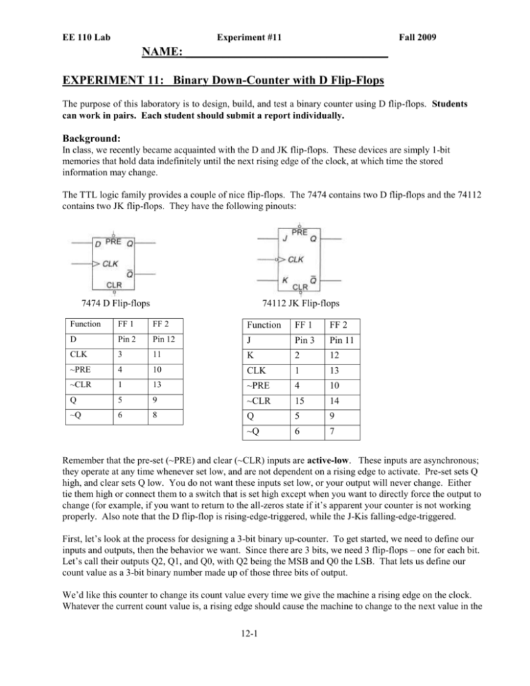
EE 110 Lab Experiment #11 Fall 2009 NAME: _________________________________ EXPERIMENT 11: Binary Down-Counter with D Flip-Flops The purpose of this laboratory is to design, build, and test a binary counter using D flip-flops. Students can work in pairs. Each student should submit a report individually. Background: In class, we recently became acquainted with the D and JK flip-flops. These devices are simply 1-bit memories that hold data indefinitely until the next rising edge of the clock, at which time the stored information may change. The TTL logic family provides a couple of nice flip-flops. The 7474 contains two D flip-flops and the 74112 contains two JK flip-flops. They have the following pinouts: 7474 D Flip-flops 74112 JK Flip-flops Function FF 1 FF 2 Function FF 1 FF 2 D Pin 2 Pin 12 J Pin 3 Pin 11 CLK 3 11 K 2 12 ~PRE 4 10 CLK 1 13 ~CLR 1 13 ~PRE 4 10 Q 5 9 ~CLR 15 14 ~Q 6 8 Q 5 9 ~Q 6 7 Remember that the pre-set (~PRE) and clear (~CLR) inputs are active-low. These inputs are asynchronous; they operate at any time whenever set low, and are not dependent on a rising edge to activate. Pre-set sets Q high, and clear sets Q low. You do not want these inputs set low, or your output will never change. Either tie them high or connect them to a switch that is set high except when you want to directly force the output to change (for example, if you want to return to the all-zeros state if it’s apparent your counter is not working properly. Also note that the D flip-flop is rising-edge-triggered, while the J-Kis falling-edge-triggered. First, let’s look at the process for designing a 3-bit binary up-counter. To get started, we need to define our inputs and outputs, then the behavior we want. Since there are 3 bits, we need 3 flip-flops – one for each bit. Let’s call their outputs Q2, Q1, and Q0, with Q2 being the MSB and Q0 the LSB. That lets us define our count value as a 3-bit binary number made up of those three bits of output. We’d like this counter to change its count value every time we give the machine a rising edge on the clock. Whatever the current count value is, a rising edge should cause the machine to change to the next value in the 12-1 EE 110 Lab Experiment #11 Fall 2009 count sequence. If we’re at 000 and give a clock pulse, we should see the machine change to 001. The following state table describes what we want to happen for every case. Present State Value Q2 0 1 2 3 4 5 6 7 0 0 0 0 1 1 1 1 Q1 Next State Value Q0 Q2* 0 0 1 0 0 1 2 0 1 0 3 0 1 1 4 1 0 0 5 1 0 1 6 1 1 0 7 1 1 1 0 0 Table 1: State Table for Binary 3-bit Up-Counter Q1* Q0* 0 1 1 0 0 1 1 0 1 0 1 0 1 0 1 0 Let’s assume we’re going to use D flip-flops. We’re going to wire all the flip-flops to a common clock as follows: The next state of the D flip-flop will be whatever its D input is: Q* = D . So we can use this to define what the D2, D1, and D0 inputs must be in order to produce the desired next state: Q2*, Q1*, and Q0*. This gives us the following equations: Q2* = D2 Q1* = D1 Q0* = D0 So how can we produce the necessary D inputs? Easy. Use a K-map to produce minimized Boolean expressions for each D input according to the state table above. Once we have these equations, it’s a simple matter of drawing the complete logic diagram and building the circuit. Pre-Lab Procedure for 3-bit Down-Counter: 1) Complete the following state table (on the next page) to define the behavior of a down-counter. Each transition should decrement (decrease by 1) the count value. A zero value should wrap around to produce 7 when clocked. 12-2 EE 110 Lab Experiment #11 Present State Value Q2 Q1 Q0 0 1 2 3 4 5 6 7 0 0 0 0 1 1 1 1 0 0 1 1 0 0 1 1 0 1 0 1 0 1 0 1 Fall 2009 Next State Value Q2* Q1* Q0* Table 1: State transition table of a 3-bit binary down counter. 2) You’re going to use D flip-flops to realize this counter. Derive minimized Boolean expressions for all three D inputs: D2, D1, and D0. (Use K-maps.) 12-3 EE 110 Lab Experiment #11 Fall 2009 3) Draw the schematic for your complete 3-bit counter. Label all pin numbers and chip types. You want to make sure this counter is clearly defined and as easy to build as possible. Figure 1: Complete schematic diagram of 3-bit binary down counter. Lab Procedure: 12-4 EE 110 Lab Experiment #11 Fall 2009 1) Build your counter. Wire the Q outputs to LEDs and/or the 7-segment display. Connect your clock input to the pulse switch, so each press and release of the switch gives you exactly one clock cycle. To ensure a good clock signal, you should buffer the output of the pulse switch. Complete the following table according to the behavior you observe. Present State Value Q2 Q1 Q0 0 1 2 3 4 5 6 7 0 0 0 0 1 1 1 1 0 0 1 1 0 0 1 1 0 1 0 1 0 1 0 1 Next State Value Q2* Q1* Q0* Table 2: State Table for Observed Behavior of 3-bit Binary Down-Counter 2) Wire the clear line of all flip-flops to the other pulse switch such that pressing the switch asserts the clear function. Remember that the clear input is active low. Exercise the circuit by operating the clock and clear buttons. What do you observe? ______________________________________________________________________________ ______________________________________________________________________________ 3) Disconnect the clock input from your pulse switch and connect it to the output of the function generator. Make sure the function generator is producing a square wave of at least 3 volts positive. Set the frequency to the lowest setting. Look at the waveform on the scope. To get your counter to work from the function generator, the signal must be very clean. Most of our function generators don’t produce good enough output signals. However, it’s relatively easy to clean it up by buffering it. Run the function generator output through a spare gate, check the output to make sure it’s nice and clean on the scope (no oscillation, noise, or decay), then feed it to your circuit’s clock input. What do you observe? ______________________________________________________________________________ ______________________________________________________________________________ Now change the clock frequency to something fast -- higher than 10 KHz. You won’t be able to watch the LEDs change because it happens too rapidly for your eye to catch. Use the oscilloscope to display the action of the three output bits against the clock. You’ll have to use one of the input pods in order to obtain more than two input channels on the scope. 4) Demonstrate the operation of your circuit to the teaching assistant or professor. Get their signature and comments regarding the functionality of your circuits. 12-5 EE 110 Lab Experiment #11 Fall 2009 TA Signature: _______________________________________________________________ 5) Complete the following: a. What results did you obtain in this experiment? b. What difficulties did you have? c. What are your conclusions? What did you learn about designing counters? 12-6
