INTRODUCTION TO AREA CLASSIFICATION
advertisement
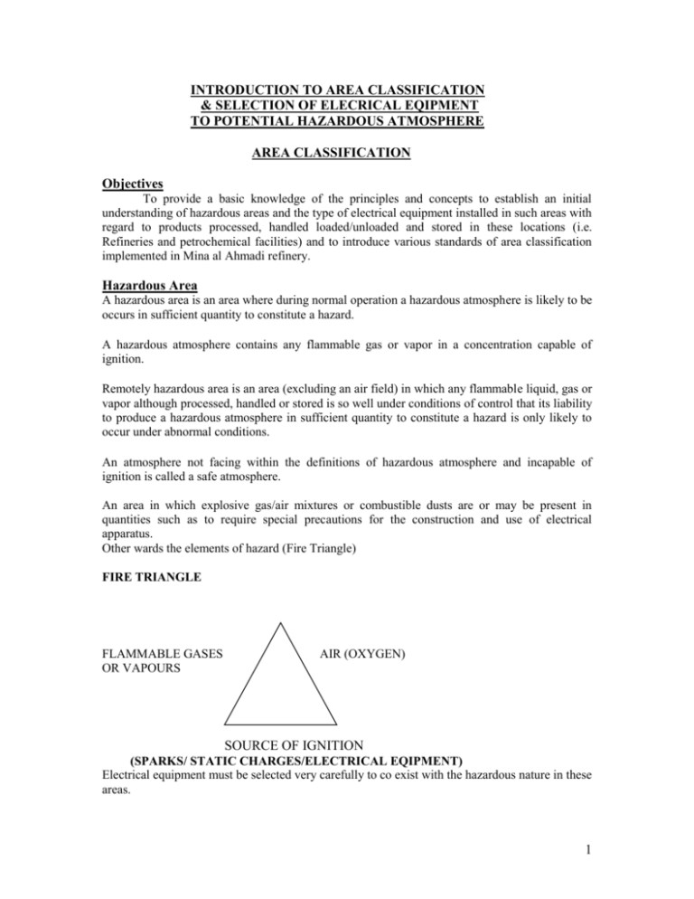
INTRODUCTION TO AREA CLASSIFICATION & SELECTION OF ELECRICAL EQIPMENT TO POTENTIAL HAZARDOUS ATMOSPHERE AREA CLASSIFICATION Objectives To provide a basic knowledge of the principles and concepts to establish an initial understanding of hazardous areas and the type of electrical equipment installed in such areas with regard to products processed, handled loaded/unloaded and stored in these locations (i.e. Refineries and petrochemical facilities) and to introduce various standards of area classification implemented in Mina al Ahmadi refinery. Hazardous Area A hazardous area is an area where during normal operation a hazardous atmosphere is likely to be occurs in sufficient quantity to constitute a hazard. A hazardous atmosphere contains any flammable gas or vapor in a concentration capable of ignition. Remotely hazardous area is an area (excluding an air field) in which any flammable liquid, gas or vapor although processed, handled or stored is so well under conditions of control that its liability to produce a hazardous atmosphere in sufficient quantity to constitute a hazard is only likely to occur under abnormal conditions. An atmosphere not facing within the definitions of hazardous atmosphere and incapable of ignition is called a safe atmosphere. An area in which explosive gas/air mixtures or combustible dusts are or may be present in quantities such as to require special precautions for the construction and use of electrical apparatus. Other wards the elements of hazard (Fire Triangle) FIRE TRIANGLE FLAMMABLE GASES OR VAPOURS AIR (OXYGEN) SOURCE OF IGNITION (SPARKS/ STATIC CHARGES/ELECTRICAL EQIPMENT) Electrical equipment must be selected very carefully to co exist with the hazardous nature in these areas. 1 Procedure for selecting Electrical Apparatus:Electrical apparatus should be selected for use in hazardous area in accordance with each of the following criteria:a) The type of protection of the apparatus in relation to the area classification of the hazardous area. b) The temperature classification of the apparatus in relation to the ignition temperature of the gases and vapors involved. c) The apparatus gas group (where applicable) in relation to the relevant properties of the gases and vapors involved. d) The apparatus construction and enclosure in relation to the environmental conditions. A) Selection of electrical apparatus according to type of protection and area classification There are 2 standards for area classification implemented in MAA refinery. 1. European standards in Old refinery and Gas liquids 2. American standards in RMP and FUP areas. European Standards (Mainly BS4683 & BS 5501) and IEC 79. Hazardous area is classified into 3 zones Zone0 A zone in which an explosive gas/air mixture is continuously present or present for long periods (estimated to be more than 1000Hr). Locations: - inside closed tanks, closed process vessels or containers which contain flammable gases, vapors and/or liquids. Zone1 A zone in which an explosive gas/air mixture is likely to occur in normal operation. (Estimated to be in between 10 to 1000Hr). This classification is applied to areas in which a hazardous atmosphere is likely to occur at any time and therefore requires application of measures to prevent the occurrence of an hazardous electrical condition at any time and at any circumstances. Locations: - Above storage tanks, relief valves, vents or devices which are likely to release flammable gases and vapors under normal condition. Also in a Zone2 area where any situations which allows a hazardous atmosphere to collect such as a pit or trench although it may be in open air shall be classified as Zone1 area. Especially since the heavy vapors travel along distances if air currents do not assist diffusion. Zone 2 A zone in which an explosive gas/air mixture is not likely to occur in normal operation and if it occurs it will exist only for a short time. (Estimated < 10 hr/year). ‘i.e. A hazardous atmosphere is likely to occur only under abnormal operating conditions. This is applicable only where a fire as an explosion hazard is unlikely and may be caused only by the simultaneous and improbable occurrence of an arc or spark resulting from an electrical failure and a hazardous atmosphere arising through the failure of the conditions of control. Locations: - Pumps, valves, compressors, around tanks and vessels etc. Unclassified area: The area which has no hazardous (safe area) American Standards (NEC 500):Hazardous area is classified into 3 classes Class I Locations in which flammable gases or vapors are or may be present. 2 Class II Locations which are hazardous because of the presence of combustible dust. Class III Locations where hazardous conditions exists because of ignitable fibers or flyings. Within each class NEC recognizes two divisions. Regarding class1. Division1:The criteria for these locations is that they are likely to have flammable gases or vapors present under normal conditions. Division 2: The criteria for these locations are that they are likely to have flammable gases or vapors present only under abnormal conditions. IEC 79-10 Gases vapors And mist Dusts Fibers and Flying Zone 0 Zone 1 Zone 2 Zone 10 Zone 11 as for dusts USA ( to NEC) Division1 Class1 Division 2 Division 1 Class II Division 2 Division 1 Class III Division 2 Electrical apparatus selected for the various hazardous locations should be of the following types: European or IEC Zone 0 Zone 1 Zone 2 Ex “ia”, Ex “s” Any type suitable for Zone 0 and Ex “d”, Ex “ib”, Ex “p”, Ex “e” & Ex“s” Any type suitable for Zone 0 and Zone 1 and Ex “N”, Ex “o”, Ex “s” Ex “d” Flame proof Enclosures designed to with stand an internal explosion of flammable gas or vapor with out suffering damage or allowing the gas or vapor surrounding the enclosure to ignite. Ex “e” Increased safety apparatus designed in such a way so as to give increased security against the possibility of sparking or excessive temperature. Ex “N” Non sparking similar in basic concept to Ex “e” Ex “i” Intrinsic safe apparatus designed in such a way as to restrict the energy to a level below that which cause ignition. Ex ‘p” Pressurizing, use of air or inert gas to maintain positive pressure to prevent the entry of flammable gas or vapor into the enclosure or room. Ex “O” Oil immersed, ignition of flammable gas or vapor is prevented by immersion of live part of apparatus in oil. Ex “q’ Sand filled, similar to oil filled, but the live part surrounded with sand or powder. Ex “s” Special protection, this concept used to permit certification of designs and mentioned above. 3 Flame proof enclosure (d):An enclosure for electrical apparatus that will withstand an internal explosion of the flammable gas or vapors which may enter it without suffering damage and without communicating the internal flammation to the external flammable gas or vapor for which it is designed. Through any joints or structural openings in the enclosure. Pressurized enclosure (p) An enclosure for electrical apparatus in which the entry of flammable gas or vapor is presented by maintaining the air (or other non flammable gases) within the enclosure at a pressure above than that of an external atmosphere. Intrinsic safety (i) A circuit or part of the circuit is intrinsically safe when spark or thermal effect produced normally (i.e. By breaking or closing the circuit) or accidentally (ex. By short circuit or earth fault) incapable under prescribed test conditions, if causing ignition of a prescribed gas or vapor. Sand filled apparatus (Q) Electrical apparatus which has all its live parts entirely embedded in a mass of powdery material, in such a way that if, under the conditions of use for which the apparatus has been designed, an arc occurs within the enclosure, the arc will not be liable to ignite the outer explosive atmosphere, either by transmission of flame or by the overheating of the walls of the enclosure. Oil immersed apparatus (O) Electrical apparatus in which all such parts or the parts which may occur sparks are immersed in oil to sufficient depth to prevent ignition of an explosive gas mixture that may be present above the surface of the oil, and all live parts are either immersed in oil or protected by some other recognized technique. Increased safety (E) A method of protection measures in addition to those adopted in ordinary industrial practice are applied, so as to give increased security against the priority of excessive temperatures and the occurrence of arc or sparks in electrical apparatus which does not produce arcs or sparks in normal service. Non incendive (N) A type of protection applied to electrical apparatus such that in normal operation it is not capable of igniting a surrounding explosive atmosphere, and a fault capable of causing ignition not likely to occur. Out of the above for instrumentation system flame proof, intrinsic safety, increased safety, non incendive and pressurized enclosures are generally used. American (NEC) Class1, Division 1 : Explosion proof enclosures, intrinsic safe, purging and oil immersion. Class1, Division 2 : Any type suitable for div “1” and any apparatus unable of creating sparks or hot surfaces capable of ignition in “general purpose” enclosures- TEFC motors. Selection of Electrical apparatus according to temperature classification The ignition temperature is the temperature at which the ignition could occur due to a hot Surface of the apparatus depending on the type of existing gases and vapors. The 4 Maximum temperature of the exposed surface of the electrical apparatus must always be lower than the ignition temperature of the gas or vapor mixture, where it is to be used. To select an electrical apparatus, the gases can be classified to the temperature classes according to their ignition temperature. Max surface temperature < Ignition temperature of the gas. RELATION BETWEEN T CLASS AND INTERNATIONAL STANDARDS. Maximum surface temperature in deg C CENELEC BS5501 pt1 EN50 014 T1 T2 UK BS 4683 pt1 IEC 79-1 USA UL698 450 T1 T1 300 T2 T2 280 T2A 260 T2B 230 T2C 215 T2D 200 T3 T3 T3 T3 180 T3A 165 T3B 160 T3C 135 T4 T4 T4 T4 120 T4A 100 T5 T5 T5 T5 85 T6 T6 T6 T6 Note: - Unless and otherwise stated ambient temperatures to be assumed to be 40 degC. For equipment designed for use in dust locations (Class II, Groups E, and F & G), maximum allowable external temperatures are: Groups E & F 200o C. Group G, 165oC. Instruments :- all instruments through which a current or voltage signal passes, all devices in which make/ break contact occurs and any energy storing device can be considered as a source o explosion in a hazardous location. Ex :- field transmitters, field switches, thermocouples, electrical junction boxes, cables, electrical fittings, isolators local panel, local indicating instruments, magnetic flow meters, mass flow meters, analyzers etc. Selection of Apparatus According to gas grouping:1. European standards or IEC Group 1: For coal mining (methane) Group II: For gases and vapors encountered in the surface industries. Sub groups: II A (Propane) II B (Ethylene) II C (Hydrogen) 2. NEC groups D (Propane), C (ethylene), B (Hydrogen), A (Acetylene) The danger of gas increases from explosion group IIA to IIC according to IEC and from Group D to Group A to the NEC classifications. The requirements for electrical apparatus for these groups increase accordingly. Electrical apparatus certified for IIC for example is suitable for all other explosion group. Selection of apparatus according to environmental conditions:- 5 When selecting apparatus, special care should be taken to ensure that the apparatus and its components are constructed so as to guard against electrical and mechanical failures in the indeed conditions of use. Two factors to be taken into consideration. 1. Protection against ingress of solid foreign bodies. 2. Protection against ingress of liquids. Example: - IP54 means that the apparatus is protected against harmful deposits of dust (5) and splash of liquids (4). For degrees of protection see attached table. Certificate of apparatus: Legislation places for the responsibility for complying with specific safety requirements on both manufacturer and user, the usual method of demonstrating compliance is to obtain certificate from an independent recognized certifying authorities. 1. BASEEFA : UK 2. PTB : Germany 3. DEMKO : Denmark 4. Underwriters laboratory : USA 5. FM (factory manual) : USA 6. CSA : Canada 7. RIIS : Japan The certifying authority gives details of the apparatus in the certificate after carrying out required testing for samples of the apparatus. The certificate will indicate the manufactures name and address, certificate number, type number, specification number, a short description for the apparatus and where applicable the groups of gases and temperature class. The license: This document issued to the manufacturer by the certifying authorities to use the registered mark and it can be renewed every 3 years. Marking of explosion protected electrical apparatus: In addition to the standard data (make, type, serial no., electrical data), data concerning the explosion protection have to be included. In the U.S the following data to be included for explosion protected electrical apparatus to NEC 500-2: a) Class: Marking of the area of application (atmospheres where gases, vapors, dust of fibers exist) b) Group: Classification to the explosion characteristics of the materials for which the apparatus is suitable. c) Temperature or Temperature identification number: max. exposed temperature or temperature range (temperature class). FM additionally requires the marking of the designated division for intrinsic safety approval. The European standards require the following marking similar to the IEC recommendations: Example: EEx d Iib T3 EEx: - symbol for apparatus built to European standards: d :- abbreviation for the type of protection used. Iib :- group of electrical apparatus of explosion group for which it is certified. T :- temperature class. In addition the testing station and the number of the test certificate or certificate of conformity has to be stated, 6 Indian Standard (IS) In the IS standard flammable liquids whose volatility will vary and they have a flash point below 93oC and a vapor pressure not exceeding 2.81kg/cm2. These are divided into 3 classes. Class A : flammable liquids having flash point below 23oC. Class B :- flammable liquids having flash point 23 and above but below 65oC Class C :- flammable liquids having flash point 65oC and above but below 93oC Flash point is the temperature at which the oil gives so many vapors that this vapor when mixed with air, forms an ignitable mixture and gives a momentary flash on application of a small pilot flame under the specified conditions. Ignition temperature which is above flash point is the lowest temperature at which ignition causes in a mixture of explosive gas and air. The gases and vapor can be grouped under ignition groups as given below. A1 Acetane Ethane Ethyl alcohol Ethyl chloride Ethylene Ammonia Benzene (pure) Acetic acid Carbon dioxide Methane Methanol Naphthalene Propane Coal gas Toluene Water gas hydrogen A2 Acetylene Ethyl alcohol Cyclohexanone Iso anylacetate n-butane n-butylalcohol n-propyl alcohol A3 Ethyl glycol Petrol Crude oil n-hexane turpentine A4 Acetaldehyde Ethyl ethane A5 CO2 Class A :-this flammable liquids may produce large volumes of vapor when released in appreciable quantities to the open. Class B :- these liquids are heavier and less volatile than gasoline and have flash point at or slightly below normal ambient air temperature. At normal temperature some oils release vapor slowly and are hazardous only near the surface of the liquid. At elevated temperatures Class B liquids approach the characteristics of class A liquids in vapor release. Class C :- includes a broad range from cleaners solvent to heavy fuel oil in commercial grades. the degree of hazard is low because the rate of vapor release is nil at normal ambient temperature of handling and storage. 7 Safe area This can be considered as enclosed premises in which purging stream of safe atmosphere is continuously maintained so that no opening therein may be a point of ingress of gases or vapor coming from an external source of hazard. Pipes carrying petroleum or petroleum products laid in the open outside hazardous area can be classified as safe area. Area in which by which combustion occurs due to process requirement such as boilers, furnaces where by nature design requires safety features of the mechanical equipment to virtually render the risk of release of hazardous gases an vapors as non existent can also be considered as safe area. General requirements of different types of protection Pressurized enclosure The method of pressurizing shall be such that the explosive mixture which have entered in the enclosure are scavenged and may not enter the enclosure during operation. The scavenging air shall be so described that no such gas may remain in the corners of the enclosure. Pressurizing system shall be so arranged that until a quantity of scavenging medium (air or inert gas) equal to the 5 times capacity of the enclosure has been passed through it, the electrical parts which might ignite the explosive mixture can not be put into operation. If scavenging stops the parts inside the enclosure which might ignite the explosive mixture shall be given. Also to take care of static charge by using proper earthing. Pressure switch cabinet Iso.valve Purge Rotameter Air filter regulator Purging prevents explosions by main-training a protective inert gas within the enclosure at a pressure that is greater than the external atmosphere. This method prevents the dangerous air/gas mixture from entering the enclosure. Pres-sure may be preserved with or without a continuous flow of the inert gas. Pressure loss or opening of enclosure cause the sys-tem to alarm or power down depending on the type of purge. There are three types of purging methods, each of which reduce the area classification within an enclosure. Type X reduces classification from Division 1 to Non-Hazardous. 8 Type Y reduces classification from Division 1 to Division 2. Type Z reduces classification from Division 2 to Non-Hazardous. Certain criteria must be met in order for a purging process to get rated as Type X, Y or Z (and thereby reduce the area classification accordingly). These criteria are listed in Figure 3-4. EXPLOSION PROOF ENCLOSURES The use of explosion-proof enclosures is a method which allows ignition to occur, but prevents any significant damaging results from the ignition. The explosion-proof enclosure contains the explosion so that it does not spread to the surroundings and cause damage to the plant and the personnel. There are bolt-on enclosures (shown) and screw-on enclosures available. Both types do not allow the explosive energy to completely escape the enclosure. Care must be taken not to mar the flanged surfaces. Also, all bolts must be torqued down correctly. One missing or loose bolt or scratched surface could pro-vide a path for the explosion to reach the outside world. Explosionproof enclosures are designed to resist the excess pressure created by an internal explosion. They are built with a variety of materials, including cast aluminum, cast iron, welded steel and stainless steel. INTRINSIC SAFETY Intrinsic Safety (I.S.) removes the ignition source from the ignition triangle. The official definition is as follows: Intrinsically safe equipment and wiring shall not be capable of releasing sufficient electrical or thermal energy under normal or abnormal conditions to cause ignition of a specific atmospheric mixture in its most easily ignited concentration. 9 Ronan’s Series X57 Intrinsic Safety Barriers eliminate the ignition source from the ignition triangle, thereby preventing combustion. There are two basic types of ignition sources. THERMAL IGNITION The first type of ignition source is thermal. A hot surface can cause ignition by spontaneous combustion. This is why every hazardous area has a temperature classification (see Table 4-1 for a full listing of all the temperature classifications). Let’s take one example of how temperature classification works. A hazardous area classified as T4 risks explosion if any surface gets hotter than 135 example, can create such a high temperature very quickly. Any piece of equipment used in-side this particular hazardous area must not be capable of generating a temperature greater than 135°C. Only equipment rated at T4, T5, or T6 would be allowed in this hazardous area. 10 IGNITION BY SPARK The second type of ignition source is the spark. Matches and cigarette lighters fall into this category. Many chemical plants place containers at the entrance where people must put their matches or lighters before entering. A spark can also be produced electronically. Any electronic device which stores or produces energy can cause a spark. Let’s discuss three different electronic ignition mechanisms in more detail. CLOSING OF CONTACTS IN CAPACITIVE CIRCUITS A capacitor stores energy in the electrical field between its plates, and this energy can present itself as a spark in the hazardous area. When the switch in Figure 4-2 is open in a capacitive circuit, the capacitor charges to a voltage “V”, and accumulates an energy equal to one-half the capacitance (C) times the square of the voltage. E = 1/2 CV 2 11 When the contacts close in a capacitive circuit to discharge a capacitor, a spark can form just before the contacts touch. Be-cause the contacts are almost touching, the size of the spark is small. The switch shown in this example can also represent field wiring which is accidently shorted. Figure A-1, in Appendix A, compares the ignition voltage to capacitance. OPENING CONTACTS IN INDUCTIVE CIRCUITS The energy stored in the magnetic field of an inductor can be released in the form of a spark in the hazardous area .With the switch in Figure 4-3 closed, the inductor L stores an energy equal to one-half the inductance times the square of the current. E = 1/2 Li 2 When the switch opens, the inductor “tries” to keep current flowing from A to B as it had been before the switch was opened. The voltage which attempts to continue this current flow is determined by the equation V = L(di/dt) The term “di/dt” is the change in cur-rent with respect to time. This number can be very large because the current will change from its previous value to zero, the instant the switch is opened. If the inductance is large, then the voltage developed (which is equal to L * did /dt)is large, and a spark could appear between the two electrodes formed by the switch opening. The switch shown in this example can also represent field wiring which is accidently cut. . OPENING AND CLOSING OF CONTACTS IN RESISTIVE CIRCUITS In this instance, shown in Figure 4-4, the ability to ignite the hazardous atmosphere depends on the open circuit voltage (V = VOC), and the short circuit current (ISC = V/R). Energy from the power supply could be released in the form of a spark at the point of the circuit opening or shorting. 12 I.S. BARRIER INTERCONNECTION As illustrated in Figure 5-1, an intrinsic safety barrier is inserted in the non-hazardous, or safe area between the instrument and the field device. The barrier blocks dangerous energy from being transmitted from the instrument to the hazardous area. This energy could be from a power supply, stored in capacitors, stored in inductors, or some combination of the three. This energy could be released due to some combination of faults (open circuits, shorts, grounds, etc.) occurring in the system. The field devices used in any hazardous area must be one of two types: Simple Apparatus - Barriers may be used with devices which qualify as “simple apparatus” without specific approval for the simple apparatus. A simple apparatus is a field device which meets the following requirements: Some examples of simple apparatus include: thermocouples, RTD’s, switches and LED’s. I.S. Certified Apparatus -Any device which does not fall into the category of simple apparatus must be I.S. Certified. This includes transmitters, current to pres-sure converters, solenoid valves, et. All Certification may come from FM, CSA, BASEEFA, or the regional qualifying agency (see chapter 8 for more details). 13 An intrinsic safety barrier is used to connect a non-certified piece of electrical equipment in a safe area to a certified or simple field device in a hazardous area. A barrier cannot be used to make an uncertified device safe in a hazardous area. If a field device is uncertified, it can have internal energy storing components. These components, in the case of a fault, may cause a spark, which in turn may start the combustion process. The barrier only protects the non-certified device in the safe area from transmitting dangerous energy to the hazardous area. In summary, the barrier is an energy limiting device placed on the electrical wires between the safe and hazardous areas. There are two basic varieties of intrinsic safety barriers: the zener barrier and the active barrier. Let’s review each of them in a little detail. ZENER BARRIER The zener diode barrier works by diverting potentially dangerous energy to ground before it can reach the hazardous area. The zener diodes limit the fault voltage to the hazardous area. There are two such diodes for redundancy. The series resistor limits current to the hazardous area, and is considered an infallible component. The arrow in Figure 5-2 shows the resultant path if excess current enters the barrier as a result of excess voltage input from the instrument. Since a zener barrier is powered by the loop and it has a current limiting resistor, it has a voltage drop across it. This barrier, in addition to protecting against dangerous energy entering the hazardous area, must allow the loop to function normally. The example in Figure 5-3 shows a 24 V, 4-20 mA transmitter loop. In this example, the sum of the voltage drops around the loop can be calculated and verified that they are less than 24 V. Instead, since the maximum resistance of the barrier is specified (RMAX END TO END), Ohm’s law is used (V = IR) to calculate the total resistance available in the loop. Either method (loop voltage or loop resistance) works identically. What we are trying to decide is whether or not the resistance of the barrier will adversely affect the loop. 14 ACTIVE BARRIER An active barrier uses transformers, optoisolators or relays to provide isolation between the hazardous area and the non-hazardous area. It does not require an intrinsically safe ground connection. Either or both the hazardous area or the non-hazardous area signals may be grounded. This may be the most logical barrier choice if a high quality I.S. grounding point is not available. Figure 5-4 shows a diagram of an active barrier. The barrier requires a 24 VDC power supply, and can typically drive larger loads than a loop powered zener barrier. REQUIREMENTS FOR INTRINSIC SAFETY Intrinsically safe systems should satisfy these requirements: u Ensure that there is a positive separation of intrinsically safe and non-intrinsically safe circuits. This prevents the ignition capable energy from intruding into the intrinsically safe circuit. 15 u Separate conduit, panduit, cable trays, etc. should be used for I.S. wiring to keep it separate from the non-I.S. wiring. If conduit is used, it must be sealed per the applicable code. This is to prevent the conduit from becoming a means of conducting flammable material from the hazardous to the non-hazardous location. I.S. wiring must always be identified. This can be performed by tagging the wires, label-ling the junction boxes, and/or color-coding the I.S. wires light blue. u Ensure that the entity parameters, upon which approval of the system is based, match up correctly. ENTITY CONCEPT The entity concept has been approved by Factory Mutual since 1978. The approval agency specifies the maximum energy a barrier can ever deliver, as well as the maximum energy a field device can ever receive and still be safe. The entity concept allows interconnection of I.S. barriers to I.S. field devices not specifically tested in such combinations. It also allows mixing of equipment from different manufacturers without additional approvals. Certification of barriers and field devices is based on the following conditions. Barrier entity parameters (from FM) must state the maximum voltage and current delivered under fault conditions. A field device entity parameter must state the maximum current and voltage which the hazardous area device can safely receive. An I.S. barrier can safely be used with a field device if it has a maximum voltage and current less than or equal to that which the field device can safely receive. All these parameters are defined by the approval agency. In addition to voltage and current, the entity parameters also include two more terms to ensure that the energy storing devices in the field do not store up a dangerous amount of energy. These terms deal with the total capacitance and total inductance of the system. A barrier has parameters which state the maximum capacitance and maximum inductance which can be safely connected to it. A field device has parameters which state the equivalent capacitance and inductance of the field device. Since wiring has capacitance and inductance, this also needs to be considered. The capacitance of the field wiring must be added to the capacitance of the field device to deter-mine whether the total capacitance for the field exceeds the maximum allowed for connecting to the I.S. barrier. The same principle applies to the inductance. 16 GROUNDING When using zener barriers, the dangerous energy is diverted to ground. There-fore, it is important to ensure a high quality intrinsic safety ground. In fact, because this grounding is so critical, two separate ground connections from each barriers are recommended, each with a resistance of less than 1 ohm. The following rules should be adhered to for I.S. grounding: diverting fault currents, they must have a good quality ground. be less than 1 ohm. ld be insulated. BASIC BARRIER SELECTION When selecting a barrier, you must ask the following questions: classification? -DC)? This is called VLOOP. -rent which can be applied to the field device (VMAX and IMAX)? These are the entity parameters of the field device assigned by FM. You will want to follow these guidelines when selecting a barrier: it will be installed. VWKG = working voltage VOC = max voltage delivered to the hazardous area ISC = max current delivered to the hazardous area VMAX = max voltage which can safely be applied to the field device IMAX= max current the field device can safely draw Figure 9-1 shows a barrier connected between an instrument in the safe area and an I.S. approved field device. The barrier can be safely used here and has full approval. During normal operating conditions, this instrument loop operates at +24 Vdc. The zener diodes in the barrier do not start to conduct any voltage to 17 ground until that voltage reaches +25.5 Vdc. Thus, under normal operating conditions, the barrier is transparent to the loop. During fault conditions, the maximum voltage the barrier can ever deliver to the hazardous area is 31.2 V. The field device is approved safe for that hazardous area if it never receives more than 35 V. The barrier ensures this. The barrier can never deliver more than 90 mA to the hazardous area during fault conditions. The field device is safe as long as it never receives more than 110 mA. The barrier ensures this as well. Therefore, because the volt-age and current entity parameters match up correctly, this loop is approved intrinsically safe. This was a little bit simplified, and did not consider the capacitance and inductance entity parameters. In reality, all the entity parameters (voltage, current, capacitance and inductance) must match up correctly in order for the loop to be approved intrinsically safe. The entity parameters are all given by the approval agency and obtained through the manufacturer. These are shown in an installation drawing. There is one installation drawing from the barrier manufacturer and one from the I.S. field device manufacturer. Both of these should be obtained by the user to ensure correct design. And keep in mind, just because the loop is safe does not mean that it works! The normal operating conditions are given by the manufacturer and are not subject to approvals. Let’s take the next step and discuss capacitance and inductance. Advanced Barrier Selection (Includes Cabling) 18 Let’s go through our first example a second time, taking into consideration capacitance and inductance. In addition to the questions asked in the basic selection, we need to ask the following: u For the field device: What is the value of the capacitance and inductance appearing at its terminals? (This is called CEQ and LEQ and is specified by FM.) u For the cables: What is the capacitance and inductance of the cable used [CCABLE (in pF/ft.), and LCABLE (in u For the barrier: What is the amount of capacitance and inductance which may be safely connected to it? This is called CA and LA and is specified by FM.) The following simple equations need to be satisfied: CEQ + CCABLE CA LEQ + LCABLE LA Figure 10-1 illustrates the previous ex-ample with capacitance and inductance taken into consideration. The maximum allowable cable capacitance, and therefore maximum allowable cable length is calculated as follows: CEQ + CCABLE CA 19 CCABLE = CA - CEQ = 5000 ft max Due to Capacitive Energy LEQ + LCABLE LA LCABLE = LA -LEQ = 2.9 mH - 2.1 mH = 0.8 mH max = 2667 ft max Due to Inductive Energy Since capacitive energy increases per unit length, 5000 ft. is the max. cable length permitted due to capacitive energy. However, inductive energy calculations result in a maximum length of 2667 ft. The ideal intrinsic safety system designer takes the capacitance and inductance into account at the beginning of the design, not as an afterthought to verify safety. The designer can calculate that capacitance and inductance allowed in the cable. Next, knowing his longest cable length, he can calculate some cable requirements. The values used in the above example (40 pF/ft. and 0.3 instrumentation cable. By defining maximum cable parameters, the designer is leaving nothing to chance. Increased safety The increased safety is permissible in all the atmospheres for instruments which have no moving current carrying parts. In atmospheres other than coal mines increased safety may be applied even for instruments with moving current carrying parts provided the rated voltage must not exceed 10volts. For increased safety type the cover plates which are meant for removing for inspection and maintenance should be fitted with special fastenings. The instruments with increased safety protection should be enclosed in cases of specially high mechanical strength. The size of window shall be as small as possible. The cover glasses shall be made of particularly tough material capable of with standing explosion pressure and should be at least 5mm thick. It should be fixed with special fastenings so that it may be replaced by special tools alone. Connection of live parts of 2.5sq.mm cross section may be made by soldering with out any support. Instruments which are not portable should have an earthing terminal on its metal housing. Non incendive Non-Incendive - Also called Simplified Protection Method in Europe, it is widely used in England. This protection method does not consider fault conditions. It assures you can not ignite a hazardous air/gas mixture during normal functioning. Devices which may spark during nor-mal operation such as relays and switches must be hermetically sealed. This safety method only applies to Division 2 areas. Non incendive circuits in which any arc or thermal effect produced under normal operating conditions are not capable of igniting the specified flammable gas or vapor in air mixture. Here the cable parameter like inductance and capacitance are controlled with in the limits specified for ignition curves (for hydrogen groups maximum current inductance allowed is 130mH at 26V, 22mA and max. capacitance allowed is 0.4 micro farad. 20
