AD/DA Converters, vibrating beam accelerometer
advertisement

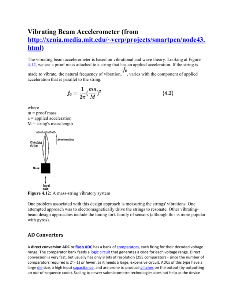
Vibrating Beam Accelerometer (from http://xenia.media.mit.edu/~verp/projects/smartpen/node43. html) The vibrating beam accelerometer is based on vibrational and wave theory. Looking at Figure 4.12, we see a proof mass attached to a string that has an applied acceleration. If the string is made to vibrate, the natural frequency of vibration, acceleration that is parallel to the string. , varies with the component of applied where m = proof mass a = applied acceleration M = string's mass/length Figure 4.12: A mass-string vibratory system One problem associated with this design approach is measuring the strings' vibrations. One attempted approach was to electromagnetically drive the strings to resonate. Other vibratingbeam design approaches include the tuning fork family of sensors (although this is more popular with gyros). AD Converters A direct conversion ADC or flash ADC has a bank of comparators, each firing for their decoded voltage range. The comparator bank feeds a logic circuit that generates a code for each voltage range. Direct conversion is very fast, but usually has only 8 bits of resolution (255 comparators - since the number of comparators required is 2n - 1) or fewer, as it needs a large, expensive circuit. ADCs of this type have a large die size, a high input capacitance, and are prone to produce glitches on the output (by outputting an out-of-sequence code). Scaling to newer submicrometre technologies does not help as the device mismatch is the dominant design limitation. They are often used for video, wideband communications or other fast signals in optical storage (from http://en.wikipedia.org/wiki/Analog-to-digital_converter) Successive approximation ADC (from http://en.wikipedia.org/wiki/Successive_Approximation_ADC) Block diagram Successive Approximation ADC Block Diagram Key DAC = digital-to-analog converter EOC = end of conversion SAR = successive approximation register S/H = sample and hold circuit Vin = input voltage Vref = reference voltage Algorithm The successive approximation Analog to digital converter circuit typically consists of four chief subcircuits: 1. A sample and hold circuit to acquire the input voltage (Vin). 2. An analog voltage comparator that compares Vin to the output of the internal DAC and outputs the result of the comparison to the successive approximation register (SAR). 3. A successive approximation register subcircuit designed to supply an approximate digital code of Vin to the internal DAC. 4. An internal reference DAC that supplies the comparator with an analog voltage equivalent of the digital code output of the SAR for comparison with Vin. The successive approximation register is initialized so that the most significant bit (MSB) is equal to a digital 1. This code is fed into the DAC which then supplies the analog equivalent of this digital code (Vref/2) into the comparator circuit for comparison with the sampled input voltage. If this analog voltage exceeds Vin the comparator causes the SAR to reset this bit and set the next bit to a digital 1. If it is lower, then the bit is left a 1 and the next bit is set to 1. This binary search continues until every bit in the SAR has been tested. The resulting code is the digital approximation of the sampled input voltage and is finally output by the ADC at the end of the conversion (EOC). Mathematically, let Vin = xVref, so x in [-1, 1] is the normalized input voltage. The objective is to approximately digitize x to an accuracy of 1/2n. The algorithm proceeds as follows: 1. Initial approximation x0 = 0. 2. ith approximation xi = xi-1 - s(xi-1 - x)/2i. where, s(x) is the signum-function(sgn(x)) (+1 for x ≥ 0, -1 for x < 0). It follows using mathematical induction that |xn - x| ≤ 1/2n. As shown in the above algorithm, a SAR ADC requires: 1. 2. 3. 4. An input voltage source Vin. A reference voltage source Vref to normalize the input. A DAC to convert the ith approximation xi to a voltage. A Comparator to perform the function s(xi - x) by comparing the DAC's voltage with the input voltage. 5. A Register to store the output of the comparator and apply xi-1 - s(xi-1 - x)/2i. Charge-Redistribution Successive Approximation ADC One of the most common implementations of the successive approximation ADC, the chargeredistribution successive approximation ADC, uses a charge scaling DAC. The charge scaling DAC simply consists of an array of individually switched binary-weighted capacitors. The amount of charge upon each capacitor in the array is used to perform the aforementioned binary search in conjunction with a comparator internal to the DAC and the successive approximation register. The DAC conversion is performed in four basic steps. 1. First, the capacitor array is completely discharged to the offset voltage of the comparator, VOS. This step provides automatic offset cancellation(i.e. The offset voltage represents nothing but dead charge which cant be juggled by the capacitors). 2. Next, all of the capacitors within the array are switched to the input signal, vIN. The capacitors now have a charge equal to their respective capacitance times the input voltage minus the offset voltage upon each of them. 3. In the third step, the capacitors are then switched so that this charge is applied across the comparator's input, creating a comparator input voltage equal to -vIN. 4. Finally, the actual conversion process proceeds. First, the MSB capacitor is switched to VREF, which corresponds to the full-scale range of the ADC. Due to the binary-weighting of the array the MSB capacitor forms a 1:1 divided between it and the rest of the array. Thus, the input voltage to the comparator is now -vIN plus VREF/2. Subsequently, if vIN is greater than VREF/2 then the comparator outputs a digital 1 as the MSB, otherwise it outputs a digital 0 as the MSB. Each capacitor is tested in the same manner until the comparator input voltage converges to the offset voltage, or at least as close as possible given the resolution of the DAC. Charge Scaling DAC DA Converters From http://en.wikipedia.org/wiki/Digital-to-analog_converter the Binary Weighted DAC, which contains one resistor or current source for each bit of the DAC connected to a summing point. These precise voltages or currents sum to the correct output value. This is one of the fastest conversion methods but suffers from poor accuracy because of the high precision required for each individual voltage or current. Such high-precision resistors and current-sources are expensive, so this type of converter is usually limited to 8-bit resolution or less. the R-2R ladder DAC, which is a binary weighted DAC that uses a repeating cascaded structure of resistor values R and 2R. This improves the precision due to the relative ease of producing equal valued matched resistors (or current sources). However, wide converters perform slowly due to increasingly large RC-constants for each added R-2R link. R-2R resistor ladder network (from http://en.wikipedia.org/wiki/Resistor_ladder) Five-bit R-2R resistor ladder A basic R-2R resistor ladder network is shown in Figure 1. The digital inputs or bits range from the most significant bit (MSB) to the least significant bit (LSB). The bits are switched between either 0V or VREF and depending on the state and location of the bits VOUT will vary between 0V and VREF minus one LSB's voltage. Because VREF is a digital signal, it is often +5V, as this is a logic 1. For a digital value VAL, of a R-2R DAC of N bits of 0V/VREF, the output voltage VOUT is: VOUT = VREF x VAL / 2^N VOUT = 5 x 3 / 4 = 3.75 Therefore, for VREF = 5V (typical TTL logic 1 voltage), N = 2 and VAL = 3 (maximum absolute number you can represent with 2 bit), we have You would expect VOUT to be able to reach VREF, but it doesn't, and there's a reason: 0V counts as a "digital step", otherwise we would have an extra step above the maximum number of steps allowed by the number of bits. The MSB causes the greatest change in output voltage and the LSB causes the smallest. The R-2R ladder is inexpensive and relatively easy to manufacture since only two resistor values are required. It is fast and has fixed output impedance R. The R-2R ladder operates as a string of current dividers whose output accuracy is solely dependent on how well each resistor is matched to the others. But a very small inaccuracy in the more significant resistors will entirely overwhelm the effect of the less significant digits changing, giving non-monotonic behavior at major crossings, such as 01111 -> 10000. Also, there will be (decoding) voltage spikes at such major crossings even with perfect resistor values. These can be filtered, with capacitance at the output node for instance; that will of course reduce the bandwidth. Also, the 2R resistance is augmented by the digital output impedances. For these reasons and doubtless others, this kind of DAC is only used with caution. In mass production the cost of a DAC chip would be small as opposed to the problems of installing and soldering numerous small parts. From http://www.analog.com/library/analogDialogue/archives/3906/Chapter%203%20Data%20Converter%20Architectures%20F.pdf


