The Step Function – Getting Started
advertisement
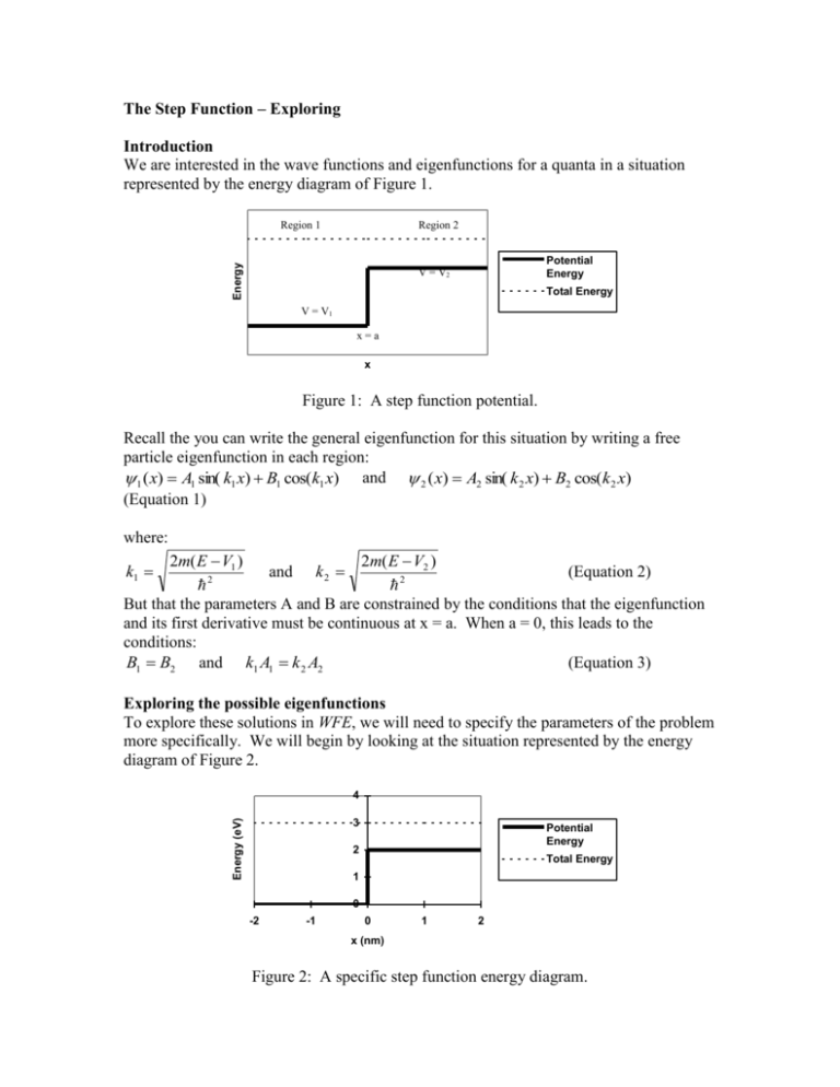
The Step Function – Exploring Introduction We are interested in the wave functions and eigenfunctions for a quanta in a situation represented by the energy diagram of Figure 1. Region 1 Energy Region 2 Potential Energy V = V2 Total Energy V = V1 x=a x Figure 1: A step function potential. Recall the you can write the general eigenfunction for this situation by writing a free particle eigenfunction in each region: 1 ( x) A1 sin( k1 x) B1 cos(k1 x) and 2 ( x) A2 sin( k 2 x) B2 cos(k 2 x) (Equation 1) where: 2m( E V1 ) 2m( E V2 ) and k 2 (Equation 2) 2 2 But that the parameters A and B are constrained by the conditions that the eigenfunction and its first derivative must be continuous at x = a. When a = 0, this leads to the conditions: (Equation 3) B1 B2 and k1 A1 k 2 A2 k1 Exploring the possible eigenfunctions To explore these solutions in WFE, we will need to specify the parameters of the problem more specifically. We will begin by looking at the situation represented by the energy diagram of Figure 2. 4 Energy (eV) 3 Potential Energy 2 Total Energy 1 0 -2 -1 0 1 2 x (nm) Figure 2: A specific step function energy diagram. In Sketcher mode, WFE allows you to set up energy diagrams like Figure 2 and easily experiment with the parameters in each region. Activity 1: Run WFE and select Sketcher from the Mode menu. In Sketcher mode, you get a graph of the energy diagram and a graph of the eigenfunction plus all of the parameters needed to set up virtually any piecewise constant potential. Set up the energy diagram shown in Figure 2 by setting the number of regions to 2, the left edge x to 2.0nm, and the total energy to 3.0eV (these three controls are on the left edge of the screen). Then set the width (w) of each region to 2.0nm, the potential energy (V) in the left region to 0.0eV, and the potential energy in the right region to 2.0eV (these controls are just under the energy graph). At the bottom of the screen are controls for k, λ, A, and B in each region. Play with the values of these controls to try to get a feel for how they affect the eigenfunction graph. (Note: if the Autoscale checkbox is checked the eigenfunction graph may rescale occasionally.) Notice that the controls for k and λ are not independent from each other. The equation type shown in each region is Asin(kx)+Bcos(kx) but can be changed. Change the equation type in the left region to a*sin(kx+b). (Recall that you have shown these to be equivilant.) Describe what A and B do to the graph in the right region. Describe what a and b do to the graph in the left region. Why is it easier to work with a and b graphically rather than A and B? Change the equation type to a*sin(kx+b) in the right region also. Although WFE allows you to set k and λ in each region to any value, Equation 2 dictates what the correct values should be given a specific energy diagram. Activity 2: Calculate k and λ for an electron in each region of Figure 2, using the values of E and V shown in the figure. (Call them k1, k2, λ1, and λ2. Use units of nm and eV.) Note: this is a calculation where the approximate equation for electrons: 1.5nm 2 eV comes in handy – it’s a nice equation to know off the top of your head. E V Set these values correctly in WFE. Make a sketch of the eigenfunction shown in WFE. Is this a valid eigenfunction? Why or why not? Although this eigenfunction is valid in each of the two regions, it is not valid overall since it is discontinuous at the boundary between the regions. To get an eigenfunction that is valid everywhere you need to adjust the parameters a and b (or A and B) in each region in order to make the function and its first derivative (slope) continuous across the boundary. Activity 3: In WFE, play with the values of a and b in each region until your eigenfunction and its first derivative is continuous across the boundary. (Note: the function will look "smooth" - with no sudden changes in slope or value when you are done.) In order to verify that you got the derivative continuous, check the Show Derivative checkbox. A second graph will appear (in orange) showing the first derivative. Verify that this is continuous across the boundary between regions. (Note: the second derivative will not be continuous - so although you should be able to get the eigenfunction and its first derivative continuous across the boundary, the derivative graph will always have a change in its slope across the boundary.) Sketch the resulting eigenfunction and write the values of a and b in each region below your sketch. Equation 3 gives the boundary conditions that you calculated algebraically in a previous exercise. If you got the eigenfunction really smooth in Activity 3 then the parameters shown in WFE should fulfill the requirements of Equation 3. Unfortunately, you’ve been working with a and b of a phase-amplitude form of the eigenfunction rather than A and B of the sine-cosine from. You would need to convert between the two in order to check to see if Equation 3 holds. (You calculated a formula to do this conversion in a previous exercise.) Fortunately, WFE can also do this conversion for you. You just need to change the equation type in both regions back to Asin(kx)+Bcos(kx) and A and B will be updated automatically. Activity 4: Change the equation type from a*sin(kx+b) to Asin(kx)+Bcos(kx) in both regions of WFE. This will convert from a and b to A and B, leaving the eigenfunction shape alone. Write the values of A and B in each region below your sketch from activity 3. Plug these values into the conditions of equation 3 to see how well your eigenfunction satisfies those conditions. Simplify both sides of each equation down to a single number. How close are the numbers on each side of the equation to being equal (calculate a percent error)? How well does this say that you were able to match boundary conditions graphically in activity 3? Matching boundary conditions graphically in WFE gives you a hands-on feeling for what the boundary conditions of Equation 3 are actually “doing” to the graph and can probably give you rather accurate results if you are careful. Of course you would probably want to solve the equations algebraically if you wanted the most accurate solutions - then you could use WFE to view those solutions. Activity 5: Randomly choose some new values of A1 and B1 to plug into Equation 3 and solve it for A2 and B2 (using the same values of k and λ as before). Plug these new values of A and B into WFE and sketch the resulting eigenfunction and its first derivative. Are they continuous? (If not try to find where you went wrong!) So far you have seen and sketched two of the possible eigenfunctions for the energy diagram of Figure 2. Remember that there are leftover free parameters after solving the boundary conditions so that there are lots of different possible eigenfunctions for this energy diagram. Activity 6: Switch the equation type in WFE back to a*sin(kx+b) in both regions. Now, change the amplitude, a, in the right region by multiplying it by some fixed amount (like 1.5 or 8 or whatever). This should make the eigenfunction (and derivative) discontinuous. Now, change a in the other region by multiplying it by that same amount. Does this make the eigenfunction (and derivative) continuous again? Why or why not? Activity 7: Switch the equation type in WFE back to Asin(kx)+Bcos(kx) in both regions and set A=1, B=0 in the left region. Change the values of A and B in the right region until the eigenfunction and its first derivative are continuous. Sketch the resulting eigenfunction. Repeat this process two more times, first beginning with A=0, B=1 in the left region, then beginning with A=1, B=1 in the left region. What is similar about these three eigenfunctions? What is different? What general hypotheses can you draw about eigenfunctions in this situation? How could you test these hypotheses? Exploring the wave functions So far you have only looked at the eigenfunctions with real parameters A and B (or a and b). In order to see the shapes and behaviors of the wave function for all possible parameters you can use the Explorer mode of WFE. Activity 8: Choose Explorer in the Mode menu of WFE. All of the parameters you set up in Sketcher mode should transfer over to Explorer mode. But recall that the Explorer mode shows the wave function not the eigenfunction. Press the run button and observe the behavior of the graphs in time. Press the stop button and sketch the wave function (real and imaginary parts) and the probability density. Press the run button and describe (using words and/or pictures) the time behavior of the wave function and probability density. Is this a stationary state? Is it a standing wave? Is it a traveling wave? Is it the same in both regions? If you look just below the run/stop button you will see that this wave function is being ‘connected’ from left to right. This means that the parameters A and B (shown just below the connect direction) only directly affect the leftmost region. In this region, the effects will be that same as you saw in the free particle case. A and B of the region to the right will be calculated using Equation 3. If you click the radio button so that the wave function is ‘connected’ from right to left then the parameters A and B on the screen will directly affect the right most region and A and B of the left region are calculated using Equation 3. Either way, WFE draws a correctly connected wave function automatically – you don’t need to worry about getting the boundary conditions right. Activity 9: Try out several different values of A and B and connect directions (both left to right and right to left). How are these wave functions similar to the one you sketched and described in Activity 8? How are they different? How are the probability densities similar to the one you sketched in Activity 8? How are they different? Study the relative amplitude of the probability density in the two regions as you change the parameters and describe any patterns you notice (you might want to review your answers to Activity 7). What is special about the wave function when the probability density has the same amplitude in both regions? What is special about the wave function when the amplitude of the probability density is most different between the two regions? Is the amplitude of the probability density ever greater in the left region? Can you figure out why? Would a classical particle be moving slower or faster in the left region? How does this fit in with your observations? (Think about the classical probability density and compare it to the quantum probability density). As with the free particle case there are many different standing wave functions in this potential. But instead of just having different phases, these standing waves have different amplitudes in the different regions - depending on their phase at the boundary between regions. Also like the free particle case, the standing wave solutions are not the ones that are analogous to the classical situation and are thus not the ones that we are most interested in. We are more interested in the possible traveling wave solutions. To study these we will use wave functions of the form: (Equation 4) ( x, t ) (Ce ikx De ikx )e iEt / rather than the sine-cosine form. There are actually four distinctly different ‘traveling wave’ solutions - which you will see in the next activity. Two of these correspond to the two classical cases of a particle coming at this potential from the left and from the right. See if you can tell which are which as you look at each of the four in turn. Activity 10: Change the equation of the left eigenfunction from Asin(kx)+Bcos(kx) to Cexp(ikx)+Dexp(-ikx). Study the shape and behavior of the wave function and probability density for the following four cases: a) Connect direction: left to right, C=1, and D=0. b) Connect direction: left to right, C=0, and D=1. c) Connect direction: right to left, C=1, and D=0. d) Connect direction: right to left, C=0, and D=1. To facilitate comparisons you may want to press the stop button and sketch the wave function and probability density then press the run button and describe how they change with time in each of the four cases. Be careful - the time dependence is different in the two different regions. How are each of these wave functions and probability density functions similar? How are they different? What physical situation do you think each represents? In all four of these cases you have a pure traveling wave in either the left or right region that is moving either left or right. In the other region you have one of those mixed waves that you learned was actually a superposition of two different traveling waves moving two different directions with two different amplitudes. When the connect direction is right to left it is the right region that is a pure traveling wave. This is because the parameters C and D directly affect the right region and you are setting one of them to zero (so in that region there is just one direction of motion). The left region parameters are set by the boundary conditions and it seems in that region neither C or D is zero. When the connect direction is left to right the situation is reversed. Recall that the exp(ikx) term represents a right moving wave so when C=1 and D=0 the waves are moving right. (And similarly, when C=0 and D=1 the waves are moving left.) Classically you expect that a particle will just move right to left (or left to right) right through the boundary - just changing speed as it crosses. So you might expect to see a pure traveling wave moving in the same direction in both regions. But there are no settings of C and D that give a pure traveling wave in both regions! (Try it and see!) Something different happens in quantum physics in this case. But one of the four preceding cases still does represent a quanta impinging on this potential from the left (and another represents a quanta impinging from the right). Final Question: Which of the four cases do you think represent these two special cases? Why? Have your answers changed from those in Activity 10? Are you more or less sure of your answers? (Hint: since none of these four cases is exactly like what we expect when we compare to a classical particle, try thinking about how a classical wave behaves at the interface between two different media.)
