2. 802.11 WLAN - Institut for Elektroniske Systemer
advertisement
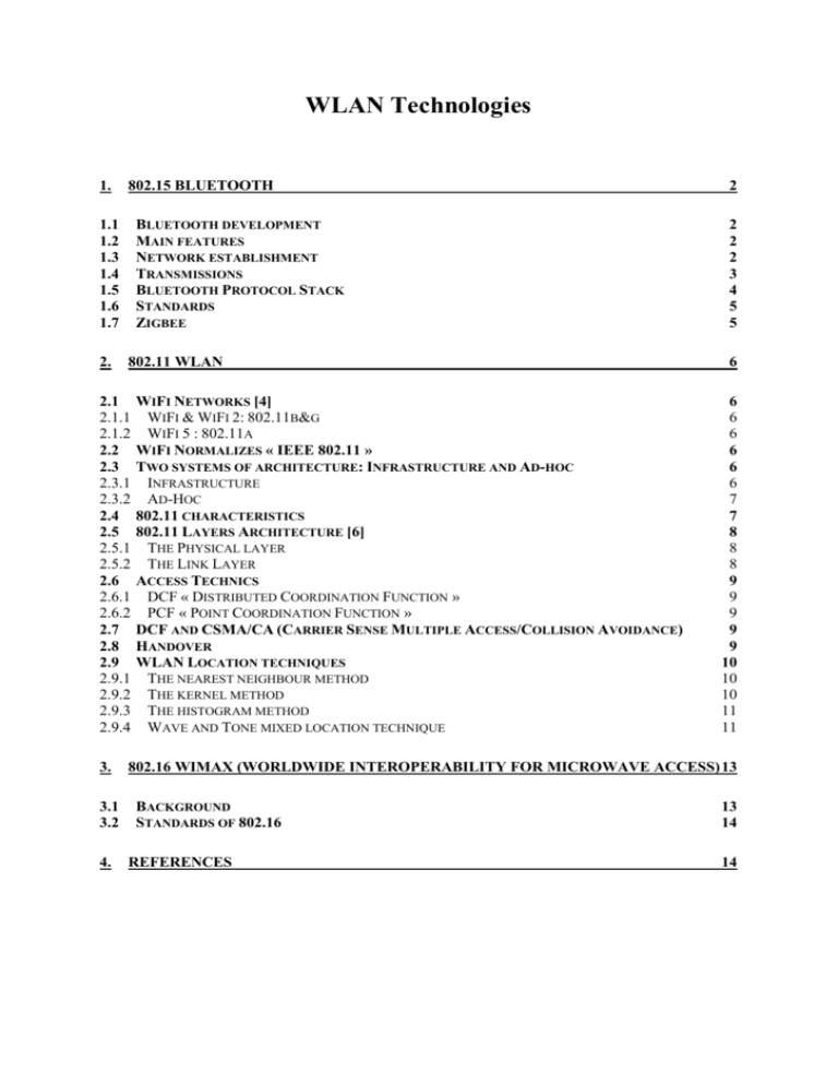
WLAN Technologies 1. 802.15 BLUETOOTH 1.1 1.2 1.3 1.4 1.5 1.6 1.7 2. BLUETOOTH DEVELOPMENT MAIN FEATURES NETWORK ESTABLISHMENT TRANSMISSIONS BLUETOOTH PROTOCOL STACK STANDARDS ZIGBEE 802.11 WLAN 2.1 2.1.1 2.1.2 2.2 2.3 2.3.1 2.3.2 2.4 2.5 2.5.1 2.5.2 2.6 2.6.1 2.6.2 2.7 2.8 2.9 2.9.1 2.9.2 2.9.3 2.9.4 3. 3.1 3.2 4. WIFI NETWORKS [4] WIFI & WIFI 2: 802.11B&G WIFI 5 : 802.11A WIFI NORMALIZES « IEEE 802.11 » TWO SYSTEMS OF ARCHITECTURE: INFRASTRUCTURE AND AD-HOC INFRASTRUCTURE AD-HOC 802.11 CHARACTERISTICS 802.11 LAYERS ARCHITECTURE [6] THE PHYSICAL LAYER THE LINK LAYER ACCESS TECHNICS DCF « DISTRIBUTED COORDINATION FUNCTION » PCF « POINT COORDINATION FUNCTION » DCF AND CSMA/CA (CARRIER SENSE MULTIPLE ACCESS/COLLISION AVOIDANCE) HANDOVER WLAN LOCATION TECHNIQUES THE NEAREST NEIGHBOUR METHOD THE KERNEL METHOD THE HISTOGRAM METHOD WAVE AND TONE MIXED LOCATION TECHNIQUE 2 2 2 2 3 4 5 5 6 6 6 6 6 6 6 7 7 8 8 8 9 9 9 9 9 10 10 10 11 11 802.16 WIMAX (WORLDWIDE INTEROPERABILITY FOR MICROWAVE ACCESS) 13 BACKGROUND STANDARDS OF 802.16 REFERENCES 13 14 14 1. 802.15 Bluetooth 1.1 Bluetooth development Bluetooth was created by Ericsson in 1994. However, it’s true start only was in 1998 with the creation of the Bluetooth SIG (Special Interest Group). The Bluetooth SIG is the reunion of several companies that have an interest in the technology and want to improve it. Hence, the Bluetooth started with the version 1.0 in1999. 1.2 Main features Bluetooth is a wireless technology. It’s considered as a WPAN (wireless personbal area network). This technology uses radio waves in ordrer to establish communications. The radio band used for the communications is part of the ISM (Industrial, Scientific & Medical), hence the use is free. The radio band used is from 2.4 GHz to 2.4835GHz; hence the bandwidth is 83.5 MHz. This bandwidth allows the creation of 79 channels for communications. The range of the Bluetooth technology is from 10 m to 100m, depending on power used. Three classes of Bluetooth have been made to distinguish the range. Class 1 2 3 Range 10 m 15-20 m 100 m Power 1 mW 2.5 mW 100 mW 1.3 Network establishment The Bluetooth network is based on the relation Master / Slave. The master will be the “chief” of a network and will make the others abide by the rules. The networks in the Bluetooth technology are called Piconet and Scatternet. A Piconet is a network of 8 Bluetooth devices with one master and 7 slaves. The master is the first connected, or the one designed if the previous master leaves. The master is the one that made the others abide the rules; it will decide the determination of the channel. Hence, it will decide the frequency and the phase of the channel. Communications are direct with the master, but slaves can not communicate directly between them. The Scatternet is different Piconets with interconnections. Indeed, a slave can have several masters and a master can be the slave of another one. fig 1.3.1 Presentation of a Piconet and a Scatternet [1] 1.4 Transmissions The bluetooth technology uses packets of 2745 bits maximum. There are three parts in the packet. fig 1.4.1 Packet in Bluetooth [2] First, the access code is the identity of the user with the information on the piconet. Second, the packet header has control information in order to have a good transmission. Third, the information that must be send. In Bluetooth, there are two kinds of transmissions: SCO and ACL. SCO stands for Synchronous Connexion Oriented, this connection is asymetric and from point to point. The SCO is more voice oriented. ACL stands for Asynchronous Connection Oriented, this is asymetric or symetric and from point to point. The ACL is more data oriented. 1.5 Bluetooth Protocol Stack The Bluetooth Protocol Stack is the following: fig 1.5.1 Bluetooth Protocol Stack [3] The main stacks in Bluetooth are: - Radio. The Radio layer defines the requirements for a Bluetooth transceiver operating in the 2.4 GHz ISM band. - Baseband. The Baseband layer describes the specification of the Bluetooth Link Controller (LC) which carries out the baseband protocols and other low-level link routines. - LMP. The Link Manager Protocol (LMP) is used by the Link Managers (on either side) for link set-up and control. - HCI. The Host Controller Interface (HCI) provides a command interface to the Baseband Link Controller and Link Manager, and access to hardware status and control registers. - L2CAP. Logical Link Control and Adaptation Protocol (L2CAP) supports higher level protocol multiplexing, packet segmentation and reassembly, and the conveying of quality of service information. - RFCOMM. The RFCOMM protocol provides emulation of serial ports over the L2CAP protocol. - SDP. The Service Discovery Protocol (SDP) provides a means for applications to discover which services are provided by or available through a Bluetooth device. It also allows applications to determine the characteristics of those available services. 1.6 Standards Bluetooth has several standards depending on the evolution of the technology. As they are in development, only the IEEE 802.15.1 is used now. However, Zigbee seems to be attractive for its low cost. IEEE 802.15.1 IEEE 802.15.2 IEEE 802.15.3 IEEE 802.15.4 commonly used Bluetooth,1 Mbit/s improvements on the radio use, not validated whereas standard of Bluetooth aiming 20 Mbit/s ( instead of 1 Mbit/s) in development, Zigbee 1.7 Zigbee Zigbee can be compared to Bluetooth. Zigbee uses the same frequency but only 16 channels. The range is the same. The debit is however less than Bluetooth, only 20 to 250 Kbit/s. However, the energy consumption is very low. As Bluetooth, Zigbee already have a group of companies with the goal of improving the technology. The group is the Zigbee alliance. 2. 802.11 WLAN 2.1 WiFi Networks [4] IEEE 802.11 is given by three generations of wireless networks: WiFi “b” (11 Mbit/s) WiFi 2 “g” (54 Mbits/s) WiFi 5 “a”(54 Mbit/s). 2.1.1 WiFi & WiFi 2: 802.11b&g For those generations, we use different frequencies around 2,4 Ghz. With those protocols, we can communicate between two stations but we can not relay the packets with a station to another terminal station, this required an access point. 2.1.2 WiFi 5 : 802.11a For this generation we use frequencies around 5 Ghz. Differences between WIFI 5 and WIFI are debit rates and techniques to relay packets. 2.2 WiFi Normalizes « IEEE 802.11 » The structure of WiFi networks is cellular. Different stations are associated to communicate directly and define a BSS « Basic Set Services » and each zone covered by terminals of a BSS defines a BSA « Basic Set Area ». 2.3 Two systems of architecture: Infrastructure and Ad-hoc 2.3.1 Infrastructure Each radiated zone is emitted by an Access Point which defines the size of the wireless network. In fact each Access point has a specific site and represents a station base for one BSS. When we have different BSS in the same wireless network, they are connected at a DS « Distribution System » by their Access Point. It is responsible for the distribution packets BSS groups connected by Distribution System define an ESS « Extented Set Service » and we can see that sub-Radio system and ESS are similar. The ESS can provide a link as a bridge for Internet access. 2.3.2 Ad-Hoc An Ad-Hoc network is constituted by terminal groups which define an IBSS « Independant Basic Set Service » to exchange information between their without infrastructure as Access Point or connections with Distribution System. Stations have some functionality as synchronisations frames. 2.4 802.11 characteristics In the following table [5], we could see the technical characteristics of WiFi technology, compared to WiMax technology. Both technologies characteristics Characteristics Definition IEEE norm Range Frequency Bandwidth Debit Rate Interferences with others radio waves Participating companies WiFi WiMax Wireless Fidelity World Interoperability for Microwave Access 802.11 802.16 300 meters 50 Km 2,4 to 5 Ghz Between 2 et 11 Ghz Up to 54 Mbits/s Up to 70 Mbits/s Possible, because of free access None, bandwidth dedicated to internet providers IBM, Intel, Dell, Microsoft, Samsung, Toshiba, Nokia, HP, Sony... Intel, Samsung, France Telecom, Fujitsu, Cisco, Siemens... WiFi and WiMax are complementary since costs of Wimax based devices are much more expansive than Wifi based devices (more than ten times bigger). Wimax is used to provide access where Wifi is still not available, but is not recommended to make a private WLAN. However, if Wimax devices costs would become to decrease, it would make a hard concurrent to the Wifi because of its large bandwidth, its bigger debit rate and its huge range of efficiency. 2.5 802.11 Layers Architecture [6] The two first layers of the 802.11 protocols are described in the following diagram: Link Layer: Physical Layer: 2.5.1 The Physical layer It is subdivided into 2 layers described bellow: The PMD layer is responsible for data encryption and modulation. The PLCP watch over the channel and notify the MAC Layer as soon as the channel is free by sending it a CCA (Clear Channel Assessment) 2.5.2 The Link Layer It is divided into 2 layers: The MAC Layer which is responsible for: Channel access control Frame formatting Error control with CRC Quality of Services Power control Mobility control Security The LLC Layer described in the following diagram: ata DSAP: Destination Access Point SSAP: Source Service Access Point Control: LLC type (with or without connexion and acquittal) The LLC Layer has two functionalities: Flow Control System Error Fixing System 2.6 Access Technics 2.6.1 DCF « Distributed Coordination Function » It’s like access techniques of traditional network with the « best-effort » method. The DCF technique is conceived to transport asynchronous data. All users can reach the network with an equal probability. 2.6.2 PCF « Point Coordination Function » This method base on polling controlled by an Access Point is conceived for significant data to manage delay for real time, voice, video or streaming. Ad-hoc use DCF and traditional wireless network use PCF and DCF. 2.7 DCF and CSMA/CA (Carrier Sense Multiple Access/Collision Avoidance) DCF is based on CSMA/CA. All devices have to support DCF method. With 802.11 Network systems, we can not used CSMA/CD like traditional Network because radio links are not « Full duplex ». That is why network use CSMA/CA with acknowledgement frames «ACK». One ACK is send by the receive station to announce that the frame is received perfectly. Support Access is controlled by the use of IFS « Inter-frame Spacing » to avoid collisions. Each terminal in the same BSS can hear another transmission. When a device send a frame, another devices update their timers « NAV: Network Allocation Network » allowing to delay the transmission. All of this procedure is defined by the back-off Algorithm. 2.8 Handover Handover in mobile communication system like GSM or UMTS is very similar as Handover in Wifi network. When a device moves to another cell, we can not stop the transmission if we want to have a great use. That is why protocol of handover is very important in mobile communication. This is the goal of mobility system. Reassociation Authentication In wireless network, we must stop the transmission between two frames to have good network performance. The standard don’t have Handover protocols but define some rules as synchronisation or association mechanism who allow to choice one Access point when a device can used different Access Point. IP addresses are managed by different network devices. 2.9 WLAN Location techniques There are three main location techniques: 1) The nearest neighbour method 2) The kernel method 3) The histogram method Before using those techniques, you must first draw a map of your room, using cases (squared-meters blocks), and make a capture of those case to make a reference model. 2.9.1 The nearest neighbour method In this technique, you would use information received by your access points, in the order of their arrival in the different access points. That means the first access point which received information of the device we be the closest of the device and so on. With this technique, you are able to define in which case of your map is your device. 2.9.2 The kernel method This technique uses probabilities to get accurate results. It is quite complicated and the accuracy of results depends on the value of σ in the kernel-based equation. More σ is lower, better is the accuracy of location results. 2.9.3 The histogram method This technique also uses probabilities. The aim of this technique is to divide the whole range of the observation variables into bins, and more the number of bins is big, more the results are accurate. Let’s take an example to compare the different results of those techniques. [7] The experimentation has been made in a closed room, 16x40 meters long, with 10 access points. The more we have access points, the more accuracy on the location you get. In a slow moving device location experimentation, the accuracy is under 2m, any else the technology used. 2.9.4 Wave and Tone mixed location technique Wlan must be associated with different techniques to improve the accuracy of devices location. First of all we can use Acoustique localisation combined with Wlan. For example: we mix two technologies and principles. A device produces 2 signals: - One radio signal to the HotSpot of the Wlan Network (This HotSpot is fixed and we know it’s position). - One 4Khz tone. We know that radio waves are faster than acoustique waves, that’s why we consider that the radio wave propagation has no delay. When the hotSpot receives the radio wave, it begins to count time. Then, the acoustique wave is received by the hotspot with the delay, so we can calculate the distance between the hotspot and the device. Each hotspot has one acoustique frequency and we can determine the distance between each others. Example : It’s very interesting to combine acoustique wave with radio wave because radio signal travels at about 300,000 kilometres per second whereas sound travels at about 340.29 meters per second which is a million times slower than radio signals. Furthermore, a one microseconde error will result in 300 meters error but for sound a one millisecond error result in only 34.03 centimetres error. However we have problems with noises interferences, path loss effects and multipath effects. That’s why we can only use this technique in indoor and must choose a good accoustique wave. 3. 802.16 WIMAX (Worldwide interoperability for microwave access) 3.1 Background The Institute of Electrical and Electronics Engineers Standards Association (IEEE-SA) sought to make BWA more widely available by developing IEEE Standard 802.16, which specifies the WirelessMAN Air Interface for wireless metropolitan area networks. The standard, which was finalized in October 2001 and was published on 8 April 2002, was created in a two-year, open-consensus process by hundreds of engineers from the world's leading operators and vendors. IEEE 802.16 addresses the "first-mile/last-mile" connection in wireless metropolitan area networks. It focuses on the efficient use of bandwidth between 10 and 66 GHz (the 2 to 11 GHz region with PMP and optional Mesh topologies by the end of 2002) and defines a medium access control (MAC) layer that supports multiple physical layer specifications customized for the frequency band of use. The 10 to 66 GHz standard supports continuously varying traffic levels at many licensed frequencies (e.g., 10.5, 25, 26, 31, 38 and 39 GHz) for two-way communications. It enables interoperability among devices, so carriers can use products from multiple vendors and warrants the availability of lower cost equipment. The draft amendment for the 2 to 11 GHz region will support both unlicensed and licensed bands. Fig. 1 Wireless StandardsThis system gives access to network WMAN from buildings equipped with antennas which communicate with the stations basic radios called BS, whereas the hosts are called SS (Subscriber Station). The exchange of information between a host and the BS are done on 2 different physical layers but the layer MAC (Medium Acces Control) manages the emission and the reception, just as the QOS. This standard allows the connection of companies or private individuals at long distances with a high flow. WiMax brings an answer appropriate to certain rural or difficult to reach zones, which are private today access to the Internet high flow for reasons of cost. This technology thus aims introducing an alternative to the DSL and the cabled networks on the one hand, and at interconnecting hot WiFi spots on the other hand. WiMax is also freed from the direct sight in urban zone in the band 3,5 GHz: it is not necessary that the transmitter and the receivers are in direct sight ("line-of-sight"); the obstacles like the buildings thus do not deteriorate the transfers of information. The IEEE set up the working group 802.16 to propose standards of network WLL (Wireless Local Loop or buckles local without wire) broad band in the line of the solutions developed for the local area networks and more particularly of Ethernet. The group then proposed frequency bands from 2 to 11 GHZ then from 11 to 66 GHZ according to uses'. 3.2 Standards of 802.16 IEEE 802.16: Finalized in December 2001. It use bandwidth from 10 to 66 GHz with line of sight (LOS) and point to point architecture. IEEE 802.16a: Finalized in January 2003. It use bandwidth from 2 to 11 Ghz with a point to multipoint architecture and no line of sight (NLOS). IEEE 802.16c: Amendment of 2002 with the basic standard IEEE 802.16e: It should appear in 2005. This standard will allow ADSL connections towards mobiles. The system will take the handover and the inter-cells change. The wireless network will use bandwidth from 2 to 8 Ghz. IEEE 802.16REVd: It will correct some errors detected in standards 802.16 and 802.16a and makes improvements to be able to support 802.16e. 4. References [1] http://csdl2.computer.org/comp/proceedings/hicss/2002/1435/02/14350061.pdf [2] http://www.zonabluetooth.com/que_es_bluetooth.htm [3] http://www.palowireless.com/infotooth/tutorial.asp [4] Networks: Best Of, Guy Pujolle [5] http://solutions.journaldunet.com/0501/050118_wimax_versus_wifi.shtml [6] WLAN: Wireless Networks & WiFi, Camille Diou, University of Metz [7] A Probabilistic Approach to WLAN User Location Estimation, Teemu Roos, Petri Myllyma¨ki, Henry Tirri, Pauli Misikangas, Juha Sieva¨nen, International Journal of Wireless Information Networks, Vol. 9, No. 3, July 2002 http://wimax.com/education/faq http://wimax.free.fr/wimax.htm ``Wireless LAN Medium Access Control (MAC) and Physical Layer (PHY) Specifications'', ANSI/IEEE Std 802.11, Aug. 1999. Jerome Galtier, ``Optimizing the IEEE 802.11b Performance using Slow Congestion Window Decrease''. 16th ITC Specialist Seminar, Anvers, Belgique, 31 august - 2 september 2004. Imad Aad, ``Quality of service in wireless local area networks'', these de doctorat, University Joseph Fourier de Grenoble, October 7, 2002. The ns-2 network simulator, http://www.isi.edu/nsnam/ns/.
