EELE 414 – Introduction to VLSI Design Homework #12 Name
advertisement
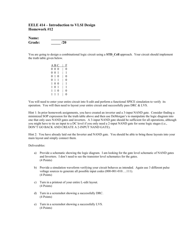
EELE 414 – Introduction to VLSI Design Homework #12 Name: Grade: __________________________ _____ /20 You are going to design a combinational logic circuit using a STD_Cell approach. Your circuit should implement the truth table given below. ABC 0 0 0 0 0 1 0 1 0 0 1 1 1 0 0 1 0 1 1 1 0 1 1 1 | | | | | | | | | F 0 1 0 0 1 1 0 0 You will need to enter your entire circuit into S-edit and perform a functional SPICE simulation to verify its operation. You will then need to layout your entire circuit and successfully pass DRC & LVS. Hint 1: In prior homework assignments, you have created an inverter and a 3-input NAND gate. Consider finding a minimized SOP expression for the truth table above and then use DeMorgan’s to manipulate the logic diagram into one that only uses NAND gates and inverters. A 3-input NAND gate should be sufficient for all operations, although you might have to tie an input to a DC level if you only need a 2-input NAND gate for some logic stages (i.e., DON’T GO BACK AND CREATE A 2-INPUT NAND GATE). Hint 2: You have already laid out the Inverter and NAND gate. You should be able to bring those layouts into your main layout and simply connect them. Deliverables: a) Provide a schematic showing the logic diagram. I am looking for the gate level schematic of NAND gates and Inverters. I don’t need to see the transistor level schematics for the gates. (4 Points) b) Provide a simulation waveform verifying your circuit behaves as intended. Again use 3 different pulse voltage sources to generate all possible input codes (000-001-010….111). (4 Points) c) Turn in a printout of your entire L-edit layout. (4 Points) d) Turn in a screenshot showing a successfully DRC. (4 Points) e) Turn in a screenshot showing a successfully LVS. (4 Points)


