Rev1part2_Design_Report_17_feb_09
advertisement
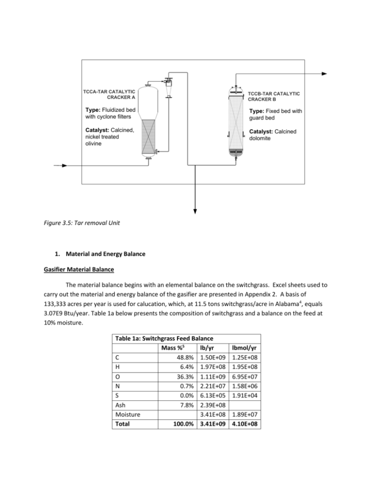
TCCA-TAR CATALYTIC CRACKER A TCCB-TAR CATALYTIC CRACKER B Type: Fluidized bed with cyclone filters Type: Fixed bed with guard bed Catalyst: Calcined, nickel treated olivine Catalyst: Calcined dolomite Figure 3.5: Tar removal Unit 1. Material and Energy Balance Gasifier Material Balance The material balance begins with an elemental balance on the switchgrass. Excel sheets used to carry out the material and energy balance of the gasifier are presented in Appendix 2. A basis of 133,333 acres per year is used for calucation, which, at 11.5 tons switchgrass/acre in Alabama4, equals 3.07E9 Btu/year. Table 1a below presents the composition of switchgrass and a balance on the feed at 10% moisture. Table 1a: Switchgrass Feed Balance Mass %5 lb/yr C 48.8% 1.50E+09 H 6.4% 1.97E+08 O 36.3% 1.11E+09 N 0.7% 2.21E+07 S 0.0% 6.13E+05 Ash 7.8% 2.39E+08 Moisture 3.41E+08 Total 100.0% 3.41E+09 lbmol/yr 1.25E+08 1.95E+08 6.95E+07 1.58E+06 1.91E+04 1.89E+07 4.10E+08 The switchgrass is fed along with a steam feed for gasification. Literature references have steam feeds of 0.4 lb/lb dry biomass6, which yields 1.23E9 lb/year in our process. The switchgrass also contains ash, the composition of which is shown in Table 1b below. Table 1b: Ash Comp. Ash lb/year SiO2 1.36E+08 Al2O3 1.91E+06 Fe2O3 8.83E+05 MgO 1.14E+07 CaO 2.64E+07 Na2O 7.16E+05 K2O 2.16E+07 P2O5 1.31E+07 Other 2.56E+07 The ash is considered inert and is parsed to the combustor in the char. To balance the material entering the gasifier, a carbon conversion rate is needed, as is the composition of the syngas from the Silvagas process. A pilot plant presents carbon conversion percentages with respect to time in Figure 1b below. Figure 1b: Carbon Conversion % of Silvagas process3 The composition of the syngas is presented in Table 1c below, along with the results of a carbon balance at 60% carbon conversion. A ratio of CO to H2O of 25 to 40 is used for the steam in the syngas.6 Tar enters the syngas as 16g/m3.1 Modeling the syngas as an ideal gas allows the mass of tar to be found. Modeling the tar as C10H8 allows a molar calculation of the tar, which is required for an accurate volume estimate. Table 1c: Composition and Balance of Syngas Mol % lbmol/yr lb/yr CO2 12.2% 1.09E+07 4.79E+08 CO 44.4% 3.96E+07 1.11E+09 H2 22.0% 1.96E+07 3.96E+07 CH4 15.6% 1.39E+07 2.23E+08 C2H4 5.1% 4.55E+06 1.28E+08 C2H6 0.7% 6.24E+05 1.88E+07 H2O 6.31E+07 1.14E+09 Tar 1.07E+06 1.38E+08 Total 100.0% 1.53E+08 3.27E+09 Other components of the syngas will include sulfur and nitrogen compounds. Several assumptions are made to balance these components. No SOx or NOx compounds are formed. 8.3% of the sulfur is sent to the char, and the rest forms 90% H2S and 10% COS. 6.6% of the nitrogen is sent to the char, and the rest forms 25% NH3, 10% HCN, and 65% N2. All chlorine forms HCl. Using these assumptions, the compositions of other components in the syngas are found and presented in Table 1d. Table 1d. Other Compounds H2S COS NH3 HCN N2 HCl Total lbmol/yr 1.58E+04 1.75E+03 3.68E+05 1.47E+05 4.79E+05 3.36E+04 1.04E+06 lb/yr 5.38E+05 2.11E+04 6.27E+06 3.98E+06 1.34E+07 1.23E+06 2.54E+07 Once the entire composition of the syngas is found, the remaining elements are parsed to the char. This char is fed to the combustor, where the combustion of C, H, and S, heats the circulating sand. The gaseous products of this combustion comprise the flue gas, the composition of which is presented in Table 1e below. Table 1e: Combustion Products lbmol/year CO2 3.89E+07 N2 4.79E+04 NO2 8.32E+03 H2O 5.82E+07 SO2 Total 1.59E+03 9.72E+07 Parsing the inert ash to an ash tray and sending the feed air to the flue gas completes the mass balance. A summary of the feed streams and product streams is shown below. Feeds: Air Introduced lbmol/year 2.95E+08 lb/year 8.50E+09 Switchgrass Feed lb/year 3.41E+09 Steam Feed lb/year lbmol/year 1.23E+09 6.81E+07 lbmol/year 2.32E+08 1.04E+07 5.82E+07 3.89E+07 7.86E+03 1.59E+03 3.40E+08 lb/year 6.50E+09 3.33E+08 1.05E+09 1.71E+09 2.36E+05 1.02E+05 9.60E+09 Products: SynGas CO2 CO H2 CH4 C2H4 C2H6 H2S COS NH3 HCN N2 HCl H2O Tar Total lbmol/year 1.09E+07 3.96E+07 1.96E+07 1.39E+07 4.55E+06 6.24E+05 1.58E+04 1.75E+03 3.68E+05 1.47E+05 4.79E+05 3.36E+04 6.31E+07 1.07E+06 1.54E+08 Mol % 7.05E+00 2.56E+01 1.27E+01 9.01E+00 2.95E+00 4.04E-01 1.02E-02 1.14E-03 2.38E-01 9.53E-02 3.10E-01 2.18E-02 4.09E+01 6.96E-01 1.00E+02 lb/year 4.79E+08 1.11E+09 3.96E+07 2.23E+08 1.28E+08 1.88E+07 5.38E+05 5.09E+04 6.27E+06 3.98E+06 1.34E+07 1.23E+06 1.14E+09 1.38E+08 3.30E+09 Flue Gas N2 O2 H2O CO2 NO2 SO2 Total Gasifier Energy Balance The gasifier’s energy balance is carried out by balancing the enthalpies of feed and product streams. The heat of formation plus the sensible heat of each stream is calculated, and the product and feed streams have to be equal in Btu/year. The switchgrass heat of formation is found as the HHV of the fuel minus the HHV of the elements comprising the fuel. The sensible heat of the switchgrass is found from a heat capacity of 0.358 Btu/lboF. The enthalpies of all other streams are found using heats of formation and Antoine Coefficients for heat capacities from literature. As beginning temperatures, literature values, of 500 oF for the steam, 220 oF for the switchgrass, 500 oF for the air feed, 1900 oF for the flue gas, and 1500 oF for the syngas.10,1 The temperatures of the syngas and flue gas are the temperatures of the gasifier and combustor, respectively. The temperatures of all streams, the carbon conversion %, the air feed rate, and the steam feed rate are all manipulated to achieve an energy balance. The results of that balance are summarized below. Switchgrass Feed T (oF) 220 Btu/year -1.1E+13 Steam Feed T (oF) 700 Btu/year -6.73E+12 Air Feed T (oF) Btu/year 500 8.62E+11 Syngas Out T (oF) 1454 Btu/year -9.1E+12 Flue Gas Out T (oF) 1770 Btu/year -7.88E+12 Ash Out T (oF) Btu/year 1770 -1.50E+10 With a heat loss of 1%, the energy in equals the energy out. The rate of sand circulation is found based on the energy of combustion of the carbon, hydrogen, and sulfur in the char. With a heat capacity of 0.378 Btu/lboF, the circulating rate is 1.13E11 lb/year, or 37 lb/lb dry biomass. In depth calculations and an illustrated summary of all streams are present in Appendix 2. All reported values lead to a complete material and energy balance, and the entire excel sheet can be manipulated by changing the basis—if a different mass rate is desired—and by manually seeking an energy balance if necessary. The sand circulation rate is found solely by an energy balance, but is comparable to a value of 36 lb/lb dry biomass found in literature for a similar process9. Though the process is modeled off of processes in literature, the final energy balance is based on thermodynamic quantities. The temperatures end up close to those found in literature1,3,6,9 based on fundamental work in the mass balance, but independent of the temperatures presented in those references. While an energy balance is carried out over the entire system, an unexplored balance exists over the gasifier. The heat of all the endothermic reactions in the gasification should equal the heat provided by the sand. As there were several variables capable of being changed to close the energy balance, this would hone the balance in on a single carbon conversion rate and should be explored. Chemical Reactor Material balances: The approach used in our model of alcohol synthesis is the Langmuir-Hinshelwood kinetic approach that can be found in many classic kinetic books [2]. Based on the following equations a mechanism is formed. The rate equations derived from these reactions are found in many textbooks and are as follows. Where And In addition to these rate equations we must have a differential equation that describes the water gas shift reaction. According to Larson [2], kwgs can be set to 10000 kmol/hr/kgcat/atm^2 and the water gas shift reaction will quickly come to equilibrium. The parameters were calculated experimentally by Gunturu [1]. The table below lists them with their units. Table2: certain parameters used in rate analysis Parameter Am, Ae, Ap, Ah Em, Ee, Ep, Eh nm, ne, np, nh K1 K2 K3 Ke Kp Kh Kz Tcp Pcpi Methanol 14.6233 143.472 3 7.64E-09 0.6785 0.9987 Ethanol 3.0518 24.986 1 Propanol 0.2148 89.3328 1 Hydrocabons Units 9.3856 mol/hr/kgcat 95.416 KJ/mol 1 0.7367 0.6086 1.2472 0.8359 46.7*(xi) 598 46.7*(xi) 46.7*(xi) 46.7*(xi) Kelvin atm Tcp and Pcpi are the temperature and partial pressure at the center point experiment. The center point experiment describes the basis for calculation of the above Parameters. Table 3:Fractional-Factorial Experimental Design Excerpt from Gunturu [1] lists experiments performed around center point condition located in last row. These experiments were used to formulate values for the parameters of the rate equations relative to the center point conditions. Once the parameters and rate equations are obtained, the gross rate equations are easily transformed into differential equations that can be solved with numerical software such as Polymath used in this example. The net rates are obtained as follows. With initial conditions: These differential equations and their initial conditions are put into Polymath and the final program can be seen in the Appendixes. The outcome is a flow rate of approximately 1800 lb/hr of ethanol from the mixed alcohol reactor. Table 4: Material Balance information on reactor Into Reactor Kmol/hr lb/hr CO 2245.532 4950.551 CO2 6.170226 13.60302 H2 2601.05 5734.333 N2 27.13115 59.81394 H2O 3578.64 7889.552 CH3OH ~0 0 C2H5OH ~0 0 C3H7OH ~0 0 CH4 394.4755 869.6697 Out of Reactor Kmol/hr lb/hr 766.3169 47321.2 38.7946 3764.064 964.8306 4287.953 27.13115 59.81394 1.258634 49.98825 5.480634 387.1307 17.7324 1800.948 2.660657 352.5019 498.6421 17636.35 Polymath program to calculate Alcohol Conversion: #Rate of formation of Methanol (Kmol/hr) d(M)/d(x2)=(Am*exp(-(Em/R)*(1/T-1/Tcp))*((Pco/Pcocp)*(Ph2/Ph2cp)^2(1/Keq)*(Pch3oh/Pch3ohcp))/(1+K1*(Pco/Pcocp)+K2*(Ph2/Ph2cp)+K3*(Pch3oh/Pch3ohcp))^nm)(Ae*exp(-(Ee/R)*(1/T-1/Tcp))*(Pch3oh/Pch3ohcp)/(1+Ke*(Pch3oh/Pch3ohcp))^ne)-(Ah*exp((Eh/R)*(1/T-1/Tcp))*(Pch3oh/Pch3ohcp)/(1+Kh*(Pch3oh/Pch3ohcp))^nh) Am=14.6233 Em=143.472 nm=3 Kcp=(Pch3ohcp)/(Pcocp*(Ph2cp)^2) Keq=Ka/(Kz*Kcp) Ka=0.99998*exp(21.225+(9143.6/T)-7.492*ln(T)+(4.076E-3*T)-(7.161E-8)*T^2) #Rate of formation of Ethanol d(E)/d(x2)=(Ae*exp(-(Ee/R)*(1/T-1/Tcp))*(Pch3oh/Pch3ohcp)/(1+Ke*(Pch3oh/Pch3ohcp))^ne)(Ap*exp(-(Ep/R)*(1/T-1/Tcp))*(Pc2h5oh/Pc2h5ohcp)/(1+Kp*(Pc2h5oh/Pc2h5ohcp))^np) Ae=3.0518 Ee=24.986 ne=1 #Rate of formation of Propanol d(P)/d(x2)=Ap*exp(-(Ep/R)*(1/T-1/Tcp))*(Pc2h5oh/Pc2h5ohcp)/(1+Kp*(Pc2h5oh/Pc2h5ohcp))^np Ap=0.2148 Ep=89.3328 np=1 #Rate of formation of CO2 d(c1)/d(x2)=kwgs*((Pco)*(Ph2o)-1/(Kwgs*(Pco2)*(Ph2))) c1(0)=247 #CO2 kwgs=44 Kwgs=1/exp(13.148-5639.5/T-1.077*ln(T)-0.0005446*T-0.00000011251*T^2+49170/T^2) #Rate of formation of CO d(c2)/d(x2)=-2*(Am*exp(-(Em/R)*(1/T-1/Tcp))*((Pco/Pcocp)*(Ph2/Ph2cp)^2(1/Keq)*(Pch3oh/Pch3ohcp))/(1+K1*(Pco/Pcocp)+K2*(Ph2/Ph2cp)+K3*(Pch3oh/Pch3ohcp))^nm)(Ah*exp(-(Eh/R)*(1/T-1/Tcp))*(Pch3oh/Pch3ohcp)/(1+Kh*(Pch3oh/Pch3ohcp))^nh)-2*((Ae*exp((Ee/R)*(1/T-1/Tcp))*(Pch3oh/Pch3ohcp)/(1+Ke*(Pch3oh/Pch3ohcp))^ne))-2*(Ap*exp(-(Ep/R)*(1/T1/Tcp))*(Pc2h5oh/Pc2h5ohcp)/(1+Kp*(Pc2h5oh/Pc2h5ohcp))^np)+(kwgs*((Pco)*(Ph2o)1/(Kwgs*(Pco2)*(Ph2)))) c2(0)=2245.530 #CO #Rate of formation of H2 d(c3)/d(x2)=-((Am*exp(-(Em/R)*(1/T-1/Tcp))*((Pco/Pcocp)*(Ph2/Ph2cp)^2(1/Keq)*(Pch3oh/Pch3ohcp))/(1+K1*(Pco/Pcocp)+K2*(Ph2/Ph2cp)+K3*(Pch3oh/Pch3ohcp))^nm))((Ae*exp(-(Ee/R)*(1/T-1/Tcp))*(Pch3oh/Pch3ohcp)/(1+Ke*(Pch3oh/Pch3ohcp))^ne))-(Ap*exp((Ep/R)*(1/T-1/Tcp))*(Pc2h5oh/Pc2h5ohcp)/(1+Kp*(Pc2h5oh/Pc2h5ohcp))^np)-(kwgs*((Pco)*(Ph2o)1/(Kwgs*(Pco2)*(Ph2)))) c3(0)=2601.05 #H2 #Rate of formation of CH4 d(c4)/d(x2)=Ah*exp(-(Eh/R)*(1/T-1/Tcp))*(Pch3oh/Pch3ohcp)/(1+Kh*(Pch3oh/Pch3ohcp))^nh c4(0)=394.476 #CH4 Ah=9.3856 Eh=95.416 nh=1 #Rate of formation of N2 = 0 d(c7)/d(x2)=0 c7(0)=27.1311 #N2 #Rate of formation of H2O d(c8)/d(x2)=(Ah*exp(-(Eh/R)*(1/T1/Tcp))*(Pch3oh/Pch3ohcp)/(1+Kh*(Pch3oh/Pch3ohcp))^nh)+((Ae*exp(-(Ee/R)*(1/T1/Tcp))*(Pch3oh/Pch3ohcp)/(1+Ke*(Pch3oh/Pch3ohcp))^ne))+(Ap*exp(-(Ep/R)*(1/T1/Tcp))*(Pc2h5oh/Pc2h5ohcp)/(1+Kp*(Pc2h5oh/Pc2h5ohcp))^np)-(kwgs*((Pco)*(Ph2o)1/(Kwgs*(Pco2)*(Ph2)))) c8(0)=3578.640 #H2O K1=0.0000000076393 K2=0.6785 K3=0.9987 Ke=0.7367 Kp=0.6086 Kh=1.2472 Kz=0.8359 #Tallied to keep track of partial pressures of components MolTotal=(c1+c2+c3+c4+c7+c8+M+E+P) Pco=(c2/MolTotal)*Pressure Ph2=(c3/MolTotal)*Pressure Pch3oh=(M/MolTotal)*Pressure Pc2h5oh=(E/MolTotal)*Pressure Ph2o=(c8/MolTotal)*Pressure Pco2=(c1/MolTotal)*Pressure #Temperature at the Center-Point experiment see ref [Gunturu] Tcp=598 R=8.314472 #Temperature and Pressure at conditions of NREL experiment [Phillips, et all] T=570 Pressure=67 #47.6 atm is Pressure at Center Point Experiment [Gunturu] Pcocp=47.6*(c2/MolTotal) Ph2cp=47.6*(c3/MolTotal) Pch3ohcp=47.6*(M/MolTotal) Pc2h5ohcp=47.6*(E/MolTotal) Ph2ocp=47.6*(c8/MolTotal) Pco2cp=47.6*((c1)/MolTotal) #Seeded with miniscule alcohol to prevent div by zero M(0)=0.0000000001 E(0)=0.0000000001 P(0)=0.0000000001 x2(0)=0 x2(f)=0.5 2. Data Sheet: Excel sheet attached 3. Equipment Installed Costs This is a very basic cost analysis done in accordance to the NREL report on ethanol production. The basis used was 15,000 barrels/day. These analyses will be recalculated when the final plant analysis will be done. Rough Cost Analysis: Base Year Installed cost in 2005 ($) Installed cost in 2009 ($) 2002 $ 137,228,869 $ 222,999,612 Chemical Engineering Cost Index : (Eqn 5.1) Figure 5.1: Chemical Engineering Plant cost Index 4. Constraints Review a. Conversion technology Description Gasifier Technology: The Silvagas process was chosen as a model for the gasifier. It is a dual fluidized bed system comprised of a gasifier, combustor, and two cyclones. Figure 1a below illustrates this process. Figure 1a: The Silvagas Process3 The biomass is fed into the gasifier to be gasified with steam. Hot sand from the combustor is separated from the combustor’s flue gas, and it provides the heat for the endothermic gasification reactions. Some of the carbon from the biomass is gasified into the syngas, creating the useful product. Unconverted biomass is separated from the syngas and fed to the combustor along with the cooled sand. The unconverted elements from the gasifier comprise the char, which is combusted with air in the combustor. This combustion heats the sand to complete the cycle.1 The Silvagas process has several advantages. It is designed for biomass gasification, and it is adaptable to forest waste, agricultural waste, municipal solid waste, and energy crops. It has short residence times with high throughputs of 3000lb/hr-ft2. It is also adaptable to wide ranges of moisture levels in the biomass feed. Finally, no pure oxygen is required with steam gasification.2 Alcohol Synthesis Technology/information: a. Catalyst: - Synthesis of ethanol from syngas The catalyst that was chosen for the synthesis of ethanol from syngas is a modified FischerTropsch catalyst specifically molybdenum disulfide bases promoted with alkali metals and cobalt (Co/MoS2). The catalyst was selected based on important characteristics. First of all, this catalyst has an ability to produce linear alcohols rather than branched alcohols. The production of linear alcohols is attributed to the presence of promoted on this catalyst. Promoters help to switch the reaction from the production of hydrocarbons to the production of linear alcohols. Another important aspect of this catalyst is its tolerance to sulfur; it can resist sulfur concentrations up to 100ppm. This quality helps to reduce the gas cleanup cost. It is important also to mention that a H2S stream must be added to maintain the catalyst activity. The catalyst must be sulfided constantly. Also, this type of catalyst has methanol decomposition functionality which means that methanol in the feed is not detrimental to the reaction and so methanol can be recycle to increase the selectivity of ethanol production. This catalyst poses a potential for higher ethanol selectivity, a high catalytic activity of 13.5% conversion of CO, and an ethanol yield of 25,900 lb/hr after adding the methanol recycle. - Synthesis of n-butanol from bimolecular ethanol condensation For the synthesis of n-butanol from ethanol, the most appropriate catalyst is the gamma alumina supported nickel specifically the 8%Ni/Al2O3 catalyst. This catalyst is prepared by adding gamma alumina to a solution of Ni(NO3)2·6H2O, then it is dried 150 °C and finally, pretreated with hydrogen at 500°C for 4hours. The most important characteristics of the type of catalyst are the low reaction temperature of just 200°C, the high selectivity to n-butanol of 64.3% which means that the byproducts have low percent selectivity as shown in table 1, the high catalytic activity that corresponds to 19.1% conversion of ethanol, and the n-butanol yield of 12.3%. Table 1 The catalytic performances of different catalysts over ethanol condensation reactions AD BD EA BO Others Sel. (%) Sel. (%) Sel. (%) Sel. (%) Sel. (%) 5.8 3.8 3.1 64.3 23.0 Catalyts 8%Ni/γ-Al2O3 a)Reaction conditions: temp: 200° C; LHSV: 0.67 h-1 b) AD: Acetaldehyde; BD: Butaldehyde; EA: Ethanyl acetate; BO: n-butanol c) Others: 2-Ethylbutanol, n-hexanol, ethyl ether, n-butyl ether etc. 5. Design Basis a. 10,000 BPD Gasoline Equivalent – Energy Content b. Clear Statement of Feedstock Production basis: Equivalent energy of 1,589,870 LPD For methanol – 3,090,866 LPD Carbon needed: 40,253 Kg/Hr For butanol – 1,894,777 LPD Carbon needed: 43,620 Kg/Hr Assuming 44,000 Kg/Hr Carbon needed covers both cases. Alcohol synthesis basis: 95% Gasifier synthesis basis: 85% Switchgrass yield basis (Dart mouth): 11.5 tons/acre 1,740,325 acres needed annually A Proper amount of steam and oxygen will be added to achieve a 2:1 molar ratio of hydrogen to carbon monoxide Requires a circular area around the plant with a radius of less than 60 miles. Plant will be located in the Midwest to keep feedstock transportation to less than 100 miles from the plant. Ideally, the plant location will have rail access. Plant will require at least 50 acres for operation and storage of switchgrass. 6. Project Communications File MEETING INFORMATION (without Advisors) Monday 26 January 2009 Meeting after class -Attendance Tim B, Tim O, Haseeb, Catalina, Greg -Agenda Assign duties for power point presentation due 27 January 2009. Assign initial research responsibilities. -Review Problems Each group member will have one slide they are responsible for and will forward said slide to Catalina NLT 2200 hrs 26 January 2009. Each group member was assigned an area of initial research responsibility to begin gathering necessary data. -Action Items N/A -Roles and Responsibilities Powerpoint Tim B -> Background Tim O -> Switchgrass Catalina -> Title page, Summary page Greg -> Block diagram, Design basis Research Tim B -> Fractionation Tim O -> Gasifier Catalina -> Alcohol Synthesis Greg -> Clean up Haseeb -> CO2 Removal -Other Ideas N/A TELECONFERENCE INFORMATION: Teleconference #3: Monday 4:00 pm 9th February 2009: Teleconference #2: Friday 3:00pm 30th January 2009: Attendance Adam Kanyuh, Dan Rusinak, David Meyers, Catalina Mogollon, Tim O’Brien, Greg Dicosola -Agenda Feedback on presentation. Assign goals and responsibilities for next week. -Review Problems Decided on mix of alcohols as product - avoid costs of distillation, have market, can still leave open to butanol. Gasification techniques - Packer engineering (Peter Schubert presentation); also Taylor gasification (will be sent through e-mail). Mass Balance- Work from catalyst type and gasifier to find rates between other steps. Consider economics of heat streams, energy coming out of process, electricity generation. What is done with every stream? Design Basis- where are we building plant? Determine economic escalation factors, units of measure. How will we price product? Set up economic values up front. Also, have assumptions of yields, etc., and impact on environment. -Roles and Responsibilities Tim O. - Gasification - decide on gasifier Catalina - Catalyst - research catalyst Greg D. - PFD Group - work on mass balance around system - work outside-in -Other Ideas N/A Monday 26 January 2009 Meeting after classAttendance Tim B, Tim O, Haseeb, Catalina, Greg -Agenda Assign duties for power point presentation due 27 January 2009. Assign initial research responsibilities. -Review Problems Each group member will have one slide they are responsible for and will forward said slide to Catalina NLT 2200 hrs 26 January 2009. Each group member was assigned an area of initial research responsibility to begin gathering necessary data. -Action Items N/A -Roles and Responsibilities Research Tim B -> Fractionation Tim O -> Gasifier Catalina -> Alcohol Synthesis Greg -> Clean up Haseeb -> CO2 Removal -Other Ideas N/A Teleconference #1: Friday 3:00pm 23rd January 2009: -Attendance Adam Kanyuh, David Myers, Tim O'Brien, Greg Dicosola, Tim Bannon -Agenda: Narrow in on Design Project in preparation of Tuesday's presentation -Review Problems: Tentative project is to design process for gasification of feedstock for production of butanol or possibly methanol. Advantages of Butanol -can be used in existing pipelines -no need to modify internal combustion engines -nearly drop in replacement for gasoline (110,000 Btu/gal) Disadvantages of Butanol -possible need of many fractionators leading to complicated project Advantages of Methanol -simpler process -can be sold for further processing Disadvantages of Methanol -may not meet project guidelines Feedstock Suggestions -municipal solid wastes or switchgrass -Action Items: Tentative process is gasification of switchgrass to produce methanol -Roles and Responsibilities: Tim B. Project Wiki, Help with Project outline Tim O. Research feedstocks Greg Block flow diagram Catalina Research feedstocks Haseeb Project Outline -Other Ideas: Narrowing project to encompass only gasifier. Black box around gasifier. 7. Information Sources and References: General References: 1. http://en.wikipedia.org/wiki/Switch_grass, Wikipedia 2. http://uicchemegroupa.wikispaces.com/file/view/switchgrass.pdf, Mark Leser, Revised Methodology for Developing Model Switchgrass Compositions. 3. http://bioenergy.ornl.gov/papers/misc/switgrs.html, Biofuels from Switchgrass: Greener Energy Pasture, Oak Ridge National Laboratory. 10 a Gasifier Technology References . Higman, C., van der Burgt, M., “Gasification.” 2003, Elsevier Science 2. Silvagas Corporation, www.silvagas.com 3. Paisley, M.A., Overend, R.P., “The Silvagas Process from Future Energy Resources—A Commercialization Success.” 2002. 4. Bioenergy Feedstock Development Program. “Biofuels from Switchgrass: Greener Energy Pastures.” Oak Ridge National Laboratory. 5. Laser, M., “Switchgrass Composition Methods.” Memo: 2004 6. Philips, S., Aden, A., Jechura, J., Dayton, D., “Thermochemical Ethanol via Indirect Gasification and Mixed Alcohol Synthesis of Lignocellulosic Biomass.” NREL: 2007 7. Basu, P., “Combustion and Gasification in Fluidized Beds.” Taylor and Francis Group: 2006 8. Kaliyan, Morey, “Strategies to Improve the Durability of Switchgrass Briquettes.” ASAE: 2007 9. Bain, R.L., “Material and Energy Balances for Methanol from Biomass Using Biomass Gasifiers.” NREL: 1992 10. Smith, J.M., Van Ness, H.C., Abbott, M.M., “Introduction to Chemical Engineering Thermodynamics.” 7th Ed. McGraw-Hill: 2005 10 b Alcohol Synthesis Technology References: [1] Gunturu, A.; et.al. ”A Kinetic Model for the Synthesis of High-Molecular-Weight Alcohols over a Sulfided Co-K-Mo/C Catalyst.” Ind. Eng. Chem. Res. Vol. 37, 1998. pp. 2107 – 2115. [2] Larson, E.D., Consonni, S., Katofsky, R.E., Iisa, K. Frederick, J., “A Cost-Benefit Assessment of Gasification-Based Biorefining in the Kraft Pulp and Paper Industry, Volume 2, Detailed Biorefinery Design and Performance Simulation”, Final Report under contract DE-FC2604NT42260 with the U.S. Department of Energy and with cost-sharing by the American Forest and Paper Association, December 2006. [3] A. Aden, P. Spath, B. Atherton, NREL Milestone Completion Report “The Potential of thermochemical Ethanol Via Mixed Alcohols Production”, (2005).
