Hoofdstuk 2
advertisement
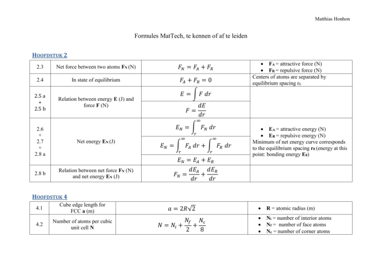
Matthias Honhon Formules MatTech, te kennen of af te leiden HOOFDSTUK 2 2.3 Net force between two atoms FN (N) 𝐹𝑁 = 𝐹𝐴 + 𝐹𝑅 2.4 In state of equilibrium 𝐹𝐴 + 𝐹𝑅 = 0 2.5 a + 2.5 b Relation between energy E (J) and force F (N) FA = attractive force (N) FR = repulsive force (N) Centers of atoms are separated by equilibrium spacing r0 𝐸 = ∫ 𝐹 𝑑𝑟 𝑑𝐸 𝑑𝑟 𝐹= ∞ 𝐸𝑁 = ∫ 𝐹𝑁 𝑑𝑟 2.6 + 2.7 + 2.8 a 2.8 b 𝑟 Net energy EN (J) ∞ 𝐸𝑁 = ∫ 𝐹𝐴 𝑑𝑟 + ∫ 𝐹𝑅 𝑑𝑟 𝑟 Relation between net force FN (N) and net energy EN (J) ∞ 𝑟 𝐸𝑁 = 𝐸𝐴 + 𝐸𝑅 𝑑𝐸𝐴 𝑑𝐸𝑅 𝐹𝑁 = + 𝑑𝑟 𝑑𝑟 EA = attractive energy (N) ER = repulsive energy (N) Minimum of net energy curve corresponds to the equilibrium spacing r0 (energy at this point: bonding energy E0) HOOFDSTUK 4 4.1 Cube edge length for FCC a (m) 𝑎 = 2𝑅√2 R = atomic radius (m) 4.2 Number of atoms per cubic unit cell N 𝑁𝑓 𝑁𝑐 𝑁 = 𝑁𝑖 + + 2 8 Ni = number of interior atoms Nf = number of face atoms Nc = number of corner atoms 4.3 Atomic packing factor APF 4.4 Cube edge length for BCC a (m) 4.5 4.6 4.7 a 4.7 b Number of atoms per hexagonal unit cell N Volume of cubic unit cell Vc (m³) Volume of hexagonal unit cell Vc (m³) 4.8 Density of metals ρ (g/cm³) 4.9 Density of ceramics ρ (g/cm³) 𝐴𝑃𝐹 = 𝑣𝑜𝑙𝑢𝑚𝑒 𝑜𝑓 𝑎𝑡𝑜𝑚𝑠 𝑖𝑛 𝑎 𝑢𝑛𝑖𝑡 𝑐𝑒𝑙𝑙 𝑉𝑆 = 𝑡𝑜𝑡𝑎𝑙 𝑢𝑛𝑖𝑐 𝑐𝑒𝑙𝑙 𝑣𝑜𝑙𝑢𝑚𝑒 𝑉𝐶 4𝑅 𝑎= √3 𝑁𝑓 𝑁𝑐 𝑁 = 𝑁𝑖 + + 2 6 3 𝑉𝑐 = 𝑎 3𝑎2 𝑐√3 𝑉𝑐 = 2 2 𝑉𝑐 = 6𝑅 𝑐√3 𝜌= 𝑛𝐴 𝑉𝑐 𝑁𝐴 𝑛′ (∑ 𝐴𝐶 + ∑ 𝐴𝐴 ) 𝜌= 𝑉𝐶 𝑁𝐴 assuming the atomic hard-sphere model R = atomic radius (m) a = cube edge (m) a = short unit cell dimension (m) c = long unit cell dimension (m) With a = 2R n = number of atoms associated with each unit cell A = atomic weight (g/mol) VC = volume of unit cell (m³) NA = Avogadro’s number (atoms/mol) n’ = number of formula units within the unit cell (all the ions included in the chemical formula unit) ∑ 𝑨𝑪 = sum of the atomic weights of all the cations in the formula unit (g/mol) ∑ 𝑨𝑨 = sum of the atomic weights of all the anions in the formula unit (g/mol) 𝑽𝑪 = unit cell volume (m³) 𝑵𝑨 = Avogadro’s number (atoms/mol) 2 4.11 Linear density LD 4.12 [110] linear density for FCC 4.13 Planar density PD 4.14 (110) planar density for FCC 𝐿𝐷 = 𝑛𝑢𝑚𝑏𝑒𝑟 𝑜𝑓 𝑎𝑡𝑜𝑚𝑠 𝑐𝑒𝑛𝑡𝑒𝑟𝑒𝑑 𝑜𝑛 𝑑𝑖𝑟𝑒𝑐𝑡𝑖𝑜𝑛 𝑣𝑒𝑐𝑡𝑜𝑟 𝑙𝑒𝑛𝑔𝑡ℎ 𝑜𝑓 𝑑𝑖𝑟𝑒𝑐𝑡𝑖𝑜𝑛 𝑣𝑒𝑐𝑡𝑜𝑟 The number of atoms per unit length whose centers lie on the direction vector for a specific crystallographic direction 2 𝑎𝑡𝑜𝑚𝑠 1 = 4𝑅 2𝑅 𝑛𝑢𝑚𝑏𝑒𝑟 𝑜𝑓 𝑎𝑡𝑜𝑚𝑠 𝑐𝑒𝑛𝑡𝑒𝑟𝑒𝑑 𝑜𝑛 𝑎 𝑝𝑙𝑎𝑛𝑒 The number of atoms per unit area that are centered on a particular crystallographic 𝑃𝐷 = 𝑎𝑟𝑒𝑎 𝑜𝑓 𝑝𝑙𝑎𝑛𝑒 plane 2 𝑎𝑡𝑜𝑚𝑠 1 𝑃𝐷110 = = 8𝑅2 √2 4𝑅2 √2 𝐿𝐷110 = HOOFDSTUK 5 extra ̅ 𝐧 (g/mol) Number-average molecular weight 𝐌 ̅𝑛 = ∑ 𝑥𝑖 𝑀𝑖 𝑀 5.6 Degree of polymerization DP ̅𝑛 𝑀 𝐷𝑃 = 𝑚 Mi = mean (middle) molecular weight of size range i (g/mol) xi = fraction of the total number of chains within the corresponding size range ̅ 𝐧 = number-average 𝐌 molecular weight (g/mol) m = repeat unit molecular weight (g/mol) Average number of repeat units in a chain HOOFDSTUK 6 6.1 Equilibrium number of vacancies Nv (vacancies/m³) 𝑄𝑣 𝑁𝑣 = N ∗ exp (− ) 𝑘𝑇 N = total number of atomic sites (atoms/m³) Qv =energy required for the formation of a vacancy (J/mol) 3 𝑁𝐴 𝜌 𝐴 6.2 Number of atomic sites per cubic meter N (atoms/m³) 𝑁= 6.3 equilibrium number of Frenkel defects Nfr (defects/m³) 𝑁𝑓𝑟 = 𝑁 exp (− 6.4 equilibrium number of Schottky defects Ns (defects/m³) 𝑁𝑠 = 𝑁 exp (− 𝑄𝑓𝑟 ) 2𝑘𝑇 𝑄𝑠 ) 2𝑘𝑇 T = absolute temperature (K) k = gas or Boltzmann’s constant= 1.38*1023 J/atom*K or 8.62*10-5 eV/atom*K NA =Avogadro’s number (atoms/mol) ρ = density (g/cm³) A = atomic weight (g/mol) Qfr = energy required for the formation of each Frenkel defect (eV/defect) k = Boltzmann’s constant = 8.62*10-5 eV/K T = absolute temperature (K) Qs = energy required for the formation of each Scottky defect (eV/defect) k = Boltzmann’s constant = 8.62*10-5 eV/K T = absolute temperature (K) In an AX-type compound HOOFDSTUK 7 7.1 Diffusion flux J (kg/m²*s or atoms/m²*s) 7.2 Fick’s first law 𝐽= 𝐽 = −𝐷 𝑀 𝐴𝑡 𝑑𝐶 𝐶𝐴 − 𝐶𝐵 = −𝐷 𝑑𝑥 𝑥𝐴 − 𝑥𝐵 M = mass or number of atoms diffusing through (g or atoms) A = area across which diffusion is occurring (m²) t = elapsed diffusion time (s) D = diffusion coefficient (m2/s) C = concentration (kg/m³) x = position within the solid (m) for constant concentrations or pressures of the diffusing species on both surfaces of the plate (CA > CB) 4 7.3 Concentration gradient ∆𝐂 ∆𝐱 (kg/m4) 7.4 a Fick’s second law 7.4 b 7.7 7.8 For diffusion situations where time and temperature are variables and composition remains constant at some value of x Diffusion coefficient D (m²/s) 𝑑𝐶 ∆𝐶 𝐶𝐴 − 𝐶𝐵 = = 𝑑𝑥 ∆𝑥 𝑥𝐴 − 𝑥𝐵 𝜕𝐶 𝜕 𝜕𝐶 = (𝐷 ) 𝜕𝑡 𝑥 𝜕𝑥 2 𝜕𝐶 𝜕 𝐶 =𝐷 2 𝜕𝑡 𝜕𝑥 𝐷𝑡 = 𝑐𝑜𝑛𝑠𝑡𝑎𝑛𝑡 𝑄𝑑 𝐷 = 𝐷0 exp (− ) 𝑅𝑇 If the diffusion coefficient is independent of composition D = diffusion coefficient (m²/s) t = elapsed diffusion time (s) D0 = temperature-independent preexponential (m²/s) Qd = activation energy for diffusion (J/mol or eV/atom) R = gas constant = 8,81 J/mol*K or 8.62*10-5 eV/atom*K T = absolute temperature (K) PM = permeability coefficient ((cm³ STP)(cm)/(cm²*s*Pa)) Δx = membrane thickness (m) ΔP = difference in pressure of the gas across the membrane (Pa) D = diffusion coefficient (m²*s) S = solubility of the diffusing species in the polymer ((cm³ STP)/Pa*cm³) 7.14 Diffusion flux for a polymer membrane J (kg/m²*s) 7.15 Permeability coefficient for small molecules in nonglassy polymers PM ((cm³ STP)(cm)/(cm²*s*Pa)) 𝐽 = −𝑃𝑀 ∆𝑃 ∆𝑥 𝑃𝑀 = 𝐷𝑆 C = concentration (kg/m³) x = position within the solid (m) 5 HOOFDSTUK 8 𝐹 𝐴0 8.1 Engineering stress or stress σ (106 N/m² or MPa) 8.2 Engineering strain ϵ (unitless or m/m or inches/inch) 8.3 Shear stress τ (MPa) extra shear strain γ γ = tan θ 8.5 Hooke’s law 𝜎 = 𝐸𝜖 𝜖= 𝑙𝑖 − 𝑙0 ∆𝑙 = 𝑙0 𝑙0 𝜏= 𝐸∝( 8.6 8.7 relation shear stress τ and shear strain γ 8.8 Poisson’s ratio υ 8.11 𝜎= Percent elongation %EL 𝐹 𝐴0 𝑑𝐹 ) 𝑑𝑟 𝑟0 𝜏 = 𝐺𝛾 𝜖𝑦 𝜖𝑥 =− 𝜖𝑧 𝜖𝑧 𝑙𝑓 − 𝑙0 %𝐸𝐿 = ( ) ∗ 100 𝑙0 𝜐=− F = instantaneous load applied perpendicular to the specimen cross section (N) A0 = original cross-sectional area before any load is applied (m²) l0 = original length before any load is applied (m or inch) li = instantaneous length (m or inch) Δl = deformation elongation (m or inch) F = load of force imposed parallel to the upper and lower faces (N) A0 = area of upper and lower faces (m²) θ = strain angle (° or radians) ϵ = engineering strain E = modulus of elasticity or Young’s modulus (GPa / gigapascal) the modulus of elasticity is proportional to the slope of the interatomic force-separation curve at the equilibrium spacing G = shear modulus, slope of the linear elastic region of the shear stress-strain curve (MPa) ratio of the lateral and axial strains l0 = original gauge length (m) lf = fracture length (m) percentage of plastic strain at fracture 6 8.12 Percent reduction in area %RA 𝐴0 − 𝐴𝑓 %𝑅𝐴 = ( ) ∗ 100 𝐴0 𝜖𝑦 𝑈𝑟 = ∫ 𝜎 𝑑𝜖 8.13 a 0 8.13 b Modulus of resilience Ur (J/m³ or Pa) 8.14 8.15 8.16 True stress σT (MPa) True strain ϵT 8.17 8.18 a 8.18 b relation true stress σT (MPa), engineering stress σ (MPa) and engineering strain ϵ relation true strain ϵT and engineering strain ϵ 1 𝑈𝑟 = 𝜎𝑦 𝜖𝑦 2 𝜎𝑦 𝜎𝑦2 1 1 𝑈𝑟 = 𝜎𝑦 𝜖𝑦 = 𝜎𝑦 ( ) = 2 2 𝐸 2𝐸 𝐹 𝜎𝑇 = 𝐴𝑖 𝑙𝑖 𝜖 𝑇 = 𝑙𝑛 𝑙0 𝐴𝑖 𝑙𝑖 = 𝐴0 𝑙0 𝜎𝑇 = 𝜎(1 + 𝜖) A0 = original cross-sectional area (m²) Af = cross-sectional area at the point of fracture (m²) strain energy per unit volume required to stress a material from an unloaded state up to the point of yielding ϵy = strain at yielding assuming a linear elastic region if no volume change occurs during deformation 𝜖 𝑇 = ln(1 + 𝜖) 8.19 true stress σT - true strain ϵT relationship in the plastic region of deformation (to the point of necking F = load (N) Ai = instantaneous cross-sectional area over which deformation is occurring (m²) l0 = original length before any load is applied (m) li = instantaneous length (m) 𝜎𝑇 = 𝐾𝜖 𝑇𝑛 K = varies from alloy to alloy and depends on the condition of the material (MPa) n = strain-hardening exponent (constant < 1) 7 HOOFDSTUK 9 9.1 a Burgers vector for FCC b 9.1 b Burgers vector for BCC b 9.1 c Burgers vector for HCP b 𝑎 ⟨110⟩ 2 𝑎 𝒃(𝐵𝐶𝐶) = ⟨111⟩ 2 𝑎 𝒃(𝐻𝐶𝑃) = ⟨112̅0⟩ 3 𝒃(𝐹𝐶𝐶) = Resolved shear stress τR (MPa) 𝜏𝑅 = 𝜎 cos 𝜙 cos 𝜆 9.3 Largest resolved shear stress τR(max) (MPa) 𝜏𝑅 (max) = 𝜎(cos 𝜙 cos 𝜆)𝑚𝑎𝑥 extra Critical resolved shear stress τcrss (MPa) if 𝜏𝑅 (max) = 𝜏𝑐𝑟𝑠𝑠 then yielding occurs 9.4 Yield strength σy (MPa) 9.6 The angle between directions 1 and 2 in cubic unit cells θ (°) 𝜃 = cos −1 [ 𝜏𝑐𝑟𝑠𝑠 (cos 𝜙 cos 𝜆)𝑚𝑎𝑥 + 𝑣12 + 𝑤12 )(𝑢22 a = unit cell edge length (m) a = unit cell edge length (m) σ = applied stress ϕ = angle between the normal to the slip plane and direction within that plane (° or radians) λ = angle between the slip and stress directions (° or radians) with most favorably oriented slip system minimum shear stress required to initiate slip property of the material that determines when yielding occurs τcrss = critical resolved shear stress (MPa) ϕ = angle between the normal to the slip plane and direction within that plane (° or radians) λ = angle between the slip and stress directions (° or radians) 𝑢1 𝑢2 + 𝑣1 𝑣2 + 𝑤1 𝑤2 √(𝑢12 a = unit cell edge length (m) 9.2 𝜎𝑦 = + 𝑣22 + 𝑤22 ) ] direction 1 = [u1v1w1] direction 2 = [u2v2w2] 8 HOOFDSTUK 10 extra Critical stress for crack propagation σc (MPa) 2𝐸𝛾𝑠 𝜎𝑐 = √ 𝜋𝑎 10.4 Fracture toughness Kc (MPa√m) 𝐾𝑐 = 𝑌𝜎𝑐 √𝜋𝑎 10.5 Plain strain fracture toughness KIc (MPa√m) 𝐾𝐼𝑐 = 𝑌𝜎√𝜋𝑎 10.6 Critical stress σc (MPa) 𝐾 𝜎𝑐 = 𝑙𝑐 𝑌√𝜋𝑎 E = modulus of elasticity (Pa) γs = specific surface energy (J/m²) a = one-half of the length of an internal crack (m) Y = dimensionless parameter that depends on both crack and specimen sizes and geometries as well as on the manner of load application σc = crack propagation (MPa) a = crack length (m) Y = dimensionless parameter that depends on both crack and specimen sizes and geometries as well as on the manner of load application σ = stress (MPa) a = crack length (m) KIc = plain strain fracture toughness (MPa√m) Y = dimensionless parameter that depends on both crack and specimen sizes and geometries as well as on the manner of load application a = crack length (m) 9 1 𝐾𝐼𝑐 2 𝑎𝑐 = ( ) 𝜋 𝜎𝑌 10.7 Maximum allowable flaw size ac (m) 10.8 Circumferential wall stress σ (MPa) 10.9 Plain strain fracture toughness KIc (MPa√m) 𝜎 𝐾𝐼𝑐 = 𝑌 ( 𝑦 ) √𝜋𝑎𝑐 𝑁 critical crack length ac (m) 𝑁 2 𝐾𝑙𝑐 𝑎𝑐 = 2 ( ) 𝑌 𝜋 𝜎𝑦 𝜎= 𝑝𝑟 2𝑡 2 10.10 KIc = plain strain fracture toughness (MPa√m) σ = stress (MPa) Y = dimensionless parameter that depends on both crack and specimen sizes and geometries as well as on the manner of load application p = pressure in the vessel (Pa) r = radius (m) t = wall thickness (m) in pressurized spherical tank Y = dimensionless parameter that depends on both crack and specimen sizes and geometries as well as on the manner of load application σy = stress (MPa) N = factor of safety ac = critical crack length (m) in pressurized spherical tank N = factor of safety Y = dimensionless parameter that depends on both crack and specimen sizes and geometries as well as on the manner of load application KIc = plain strain fracture toughness (MPa√m) σy = stress (MPa) in pressurized spherical tank 10 10.11 Plain strain fracture toughness KIc (MPa√m) 10.12 Wall thickness t (m) 10.13 Pressure in the vessel p (Pa) 𝐾𝐼𝑐 = 𝑌𝜎√𝜋𝑡 𝑡= 𝑝𝑟 2𝜎 2 𝐾𝐼𝑐2 𝑝= 2 ( ) 𝑌 𝜋𝑟 𝜎𝑦 Y = dimensionless parameter that depends on both crack and specimen sizes and geometries as well as on the manner of load application σ = stress (MPa) t = wall thickness (m) leak-before-break criterion : when onehalf the internal crack length = thickness of the pressure vessel in pressurized spherical tank p = pressure in the vessel (Pa) r = radius (m) σ = stress (MPa) leak-before-break criterion : when onehalf the internal crack length = thickness of the pressure vessel in pressurized spherical tank Y = dimensionless parameter that depends on both crack and specimen sizes and geometries as well as on the manner of load application r = radius (m) KIc = plain strain fracture toughness (MPa√m) σy = stress (MPa) in pressurized spherical tank 11 HOOFDSTUK 11 11.1 a + 11.1 b Mass fraction of the liquid phase (in the α-L phase) 𝑊𝐿 = 𝑊𝐿 = 11.2 a + 11.2 b Mass fraction of the α phase (in the α-L phase) 𝑆 𝑅+𝑆 𝐶𝛼 − 𝐶0 𝐶𝛼 − 𝐶𝐿 𝑊𝛼 = 𝑊𝛼 = C0 = overall alloy composition Distance to the other phase (here the L phase) at the same temperature, divided by the distance between the two phases at the same temperature C0 = overall alloy composition Wα = mass fraction of the alpha-phase WL = mass fraction of the liquid phase Because only two phases are present, the sum of the mass fractions must be equal to 1 𝑅 𝑅+𝑆 𝐶0 − 𝐶𝐿 𝐶𝛼 − 𝐶𝐿 𝑊𝛼 + 𝑊𝐿 = 1 11.3 𝑊𝛼 𝐶𝛼 + 𝑊𝐿 𝐶𝐿 = 𝐶0 11.4 11.5 Volume fraction of the α phase (in an alloy consisting of α and β phases) 𝑣𝛼 𝑉𝛼 = 𝑣𝛼 + 𝑣𝛽 Distance to the other phase (here the α phase) at the same temperature, divided by the distance between the two phases at the same temperature At the same temperature = horizontal line vα = volume of the α-phase in the alloy vβ = volume of the β-phase in the alloy 12 11.8 Eutectic reaction 11.9 Eutectic reaction in a leadtin alloy 11.10 Fraction of the eutectic microconstituent We 11.11 Fraction of primary α, Wα’ 11.12 Fraction of total α, Wα 11.13 Fraction of total β, Wβ 11.14 Eutectoid reaction 11.15 Peritectic reaction 11.18 Eutectic reaction in the ironiron carbide system 11.19 Eutectoid reaction in the iron-iron carbide system 𝑐𝑜𝑜𝑙𝑖𝑛𝑔 𝐿(𝐶𝐸 ) ⇌ 𝛼(𝐶𝛼𝐸 ) + 𝛽(𝐶𝛽𝐸 ) ℎ𝑒𝑎𝑡𝑖𝑛𝑔 CE = eutectic composition TE = eutectic temperature CαE = composition of the α phase at TE CβE = composition of the β phase at TE 𝑐𝑜𝑜𝑙𝑖𝑛𝑔 𝐿(61.9 𝑤𝑡% 𝑆𝑛) ⇌ 𝛼(18.3 𝑤𝑡% 𝑆𝑛) + 𝛽(97.8 𝑤𝑡% 𝑆𝑛) ℎ𝑒𝑎𝑡𝑖𝑛𝑔 𝑃 𝑃+𝑄 𝑄 𝑊𝛼′ = 𝑃+𝑄 𝑄+𝑅 𝑊𝛼 = 𝑃+𝑄+𝑅 𝑃 𝑊𝛽 = 𝑃+𝑄+𝑅 𝑊𝑒 = 𝑊𝐿 = WL = fraction of liquid from which We transforms Fraction of the α phase that existed prior to the eutectic transformation Total α = both primary and eutectic α Total β = both primary and eutectic β 𝑐𝑜𝑜𝑙𝑖𝑛𝑔 ⇌ 𝛾+𝜖 ℎ𝑒𝑎𝑡𝑖𝑛𝑔 𝑐𝑜𝑜𝑙𝑖𝑛𝑔 ⇌ 𝜖 ℎ𝑒𝑎𝑡𝑖𝑛𝑔 𝑐𝑜𝑜𝑙𝑖𝑛𝑔 𝐿 ⇌ 𝛾 + 𝐹𝑒3 𝐶 ℎ𝑒𝑎𝑡𝑖𝑛𝑔 𝑐𝑜𝑜𝑙𝑖𝑛𝑔 𝛾(0.76 𝑤𝑡% 𝐶) ⇌ 𝛼(0.022 𝑤𝑡% 𝐶) + 𝐹𝑒3 𝐶(6.7 𝑤𝑡% 𝐶) ℎ𝑒𝑎𝑡𝑖𝑛𝑔 Upon cooling, a solid phase δ transforms into two other solid phases (γ and ϵ) Upon heating, a solid phase ϵ transforms into a liquid phase L and another solid phase δ 𝛿 𝛿+𝐿 Liquid solidifies to form austenite and cementite phases Solid γ phase is transformed into α-iron and cementite 13 11.20 Fraction of pearlite Wp 11.21 Fraction of proeutectoid α, Wα 11.22 Fraction of pearlite Wp 11.23 Fraction of proeutectoid cementite WFe3C’ 𝑇 𝑇+𝑈 𝑈 𝑊𝛼′ = 𝑇+𝑈 𝑋 𝑊𝑝 = 𝑉+𝑋 𝑉 𝑊𝐹𝑒3𝐶′ = 𝑉+𝑋 𝑊𝑝 = HOOFDSTUK 12 12.1 Total free energy change ΔG 4 Δ𝐺 = 𝜋𝑟 3 Δ𝐺𝑣 + 4𝜋𝑟 2 𝛾 3 12.2 𝑑(Δ𝐺) 4 = 𝜋Δ𝐺𝑣 (3𝑟 2 ) + 4𝜋𝛾(2𝑟) = 0 𝑑𝑟 3 12.3 2𝛾 𝑟∗ = − Δ𝐺𝑣 Critical radius r* 12.4 Critical free energy ΔG* 16𝜋𝛾 3 Δ𝐺 = 3(Δ𝐺𝑣 )2 12.12 Interfacial energy γIL 𝛾𝐼𝐿 = 𝛾𝑆𝐼 + 𝛾𝑆𝐿 𝑐𝑜𝑠𝜃 ∗ ΔGv = volume free energy, the free energy change between the solid and liquid phase γ =Surface free energy ΔGv = volume free energy, the free energy change between the solid and liquid phase γ =Surface free energy ΔGv = volume free energy, the free energy change between the solid and liquid phase γ =Surface free energy Activation free energy, free energy required for the formation of a stable nucleus γSL and γSI = interfacial energies at two-phase 14 12.13 𝑟∗ = − Critical radius r* 2𝛾𝑆𝐿 𝛥𝐺𝑣 12.14 Critical free energy ΔG* 3 16𝜋𝛾𝑆𝐿 ∗ Δ𝐺 = ( ) 𝑆(𝜃) 3Δ𝐺𝑣2 12.19 Iron-iron carbide eutectoid reaction cooling 𝛾(0.76 𝑤𝑡% 𝐶) ⇌ 𝛼(0.022 𝑤𝑡% 𝐶) + 𝐹𝑒3 𝐶(6.70 𝑤𝑡% 𝐶) heating 12.20 Formation of tempered martensite 𝑚𝑎𝑟𝑡𝑒𝑛𝑠𝑖𝑡𝑒 (𝐵𝐶𝑇, 𝑠𝑖𝑛𝑔𝑙𝑒 𝑝ℎ𝑎𝑠𝑒) → 𝑡𝑒𝑚𝑝𝑒𝑟𝑒𝑑 𝑚𝑎𝑟𝑡𝑒𝑛𝑠𝑖𝑡𝑒 (𝛼 + 𝐹𝑒3 𝐶 𝑝ℎ𝑎𝑠𝑒𝑠) boundaries θ = wetting angle, angle between the γSI and γSL vectors γSL = interfacial energy γSL = interfacial energy S(θ) = function only of θ, shape of the nucleus, value between 0 and 1 HOOFDSTUK 14 14.1 fracture toughness Klc 𝐾𝑙𝑐 = 𝑌𝜎√𝜋𝑎 Y = dimensionless parameter or function that depends on both crack geometries σ = applied stress a = length of surface crack or half the length of internal crack HOOFDSTUK 15 15.1 Relaxation modulus Er(t) 𝐸𝑟 (𝑡) = 𝜎(𝑡) 𝜖0 σ(t) = measured timedependent stress ϵ0 = strain level 15 15.2 Creep modulus Ec(t) 15.4 Vulcanization 𝐸𝑐 (𝑡) = time-dependent elastic modulus for viscoelastic polymers σ0 = constant applied stress ϵ(t) = time-dependent strain 𝜎0 𝜖(𝑡) HOOFDSTUK 19 19.1 Ohm’s law 𝑉 = 𝐼𝑅 V = voltage (volts (V) or J/C) I = current, time rate of charge passage (ampere (A) or C/s) R = resistance of the material through which the current is passing (ohms or V/A) 16 19.2 + 19.3 𝜌= Electrical resistivity ρ 𝑅𝐴 𝑙 19.4 Electrical conductivity σ 19.5 Current density J 19.6 Electric field intensity E 𝑉𝐴 𝜌= 𝐼𝑙 1 𝜎= 𝜌 𝐽 = 𝜎E E= 𝑉 𝑙 ρ = electrical resistivity E = electric field intensity σ = electrical conductivity V = voltage difference between two points (volts (V) or J/C) l = distance between the two points at which the voltage is measured ρt = individual thermal resistivity contribution ρi = individual impurity resistivity contribution ρd = individual deformation resistivity contribution Q = quantity of charge stored on either plate V = voltage applied across the capacitor (volts (V) or J/C) 19.9 Matthiessen’s rule Total resistivity of a metal ρtotal 𝜌𝑡𝑜𝑡𝑎𝑙 =𝜌𝑡 + 𝜌𝑖 + 𝑝𝑑 19.24 Capacitance C (farads (F) or C/V) 𝑄 𝐶= 𝑉 R = resistance of the material through which the current is passing (ohms or V/A) A = cross-sectional area perpendicular to the direction of the current l = distance between the two points at which the voltage is measured I = current, time rate of charge passage (ampere (A) or C/s) 17 𝐴 𝐶 = 𝜖0 𝑙 19.25 Capacitance C of a parallel-plate capacitor with a vacuum in the region between the plates 19.26 Capacitance C when a dielectric material is inserted into the region within the plates 𝐶=𝜖 19.27 Dielectric constant or relative permittivity ϵr 𝜖𝑟 = 𝐴 𝑙 𝜖 𝜖0 19.28 Dipole moment p 𝑝 = 𝑞𝑑 19.29 surface charge density D0 when vacuum is present 𝐷0 = 𝜖0 E 𝐷 = 𝜖E 19.30 + 19.31 Dielectric displacement or surface density D 𝐷 = 𝜖0 E + 𝑃 19.32 Polarization P 𝑃 = 𝜖0 (𝜖𝑟 − 1)E ϵ0 = permittivity of a vacuum = 8.85 *10-12 F/m A =area of the plates l = distance between the plates ϵ = permittivity of the dielectric medium A =area of the plates l = distance between the plates ϵ = permittivity of the dielectric medium ϵ0 = permittivity of a vacuum = 8.85 *10-12 F/m q = magnitude of each dipole charge d = distance of separation between them ϵ0 = permittivity of a vacuum = 8.85 *10-12 F/m E = electric field intensity ϵ = permittivity of the dielectric medium E = electric field intensity ϵ0 = permittivity of a vacuum = 8.85 *10-12 F/m P = polarization, increase in charge density above that for a vacuum because of the presence of a dielectric ϵ0 = permittivity of a vacuum = 8.85 *10-12 F/m ϵr = dielectric constant 18 19.33 Magnitude of dipole moment for each ion pair pi 𝑝𝑖 = 𝑞𝑑𝑖 19.34 Total polarization P 𝑃 = 𝑃𝑒 + 𝑃𝑖 + 𝑃𝑜 E = electric field intensity q = charge on each ion di = relative displacement Pe = electronic polarization Pi = ionic polarization Po = orientation polarization HOOFDSTUK 20 20.1 20.3 a + 20.3 b Heat capacity C (J/mol*K or cal/mol*K) Change of length with temperature for a solid material 𝚫𝒍 𝒍𝟎 Change of volume with 20.4 𝚫𝑽 temperature 𝚫𝑽 𝟎 20.5 Heat flux or heat flow q (W/m²) 20.8 Magnitude of the stress resulting from a temperature change σ (MPa) 𝐶= 𝑑𝑄 𝑑𝑇 𝑙𝑓 − 𝑙0 = 𝛼𝑙 (𝑇𝑓 − 𝑇0 ) 𝑙0 Δ𝑙 = 𝛼𝑙 Δ𝑇 𝑙0 Δ𝑉 = 𝛼𝑣 Δ𝑇 Δ𝑉0 𝑞 = −𝑘 𝑑𝑇 𝑑𝑥 𝜎 = 𝐸𝛼𝑙 (𝑇0 − 𝑇𝑓 ) = 𝐸𝛼𝑙 Δ𝑇 dQ = energy required to produce a dT temperature change l0 = initial length (m) lf = final length (m) T0 = initial temperature (K) Tf = final temperature (K) αl = linear coefficient of thermal expansion (K-1) ΔV = volume change (m³) V0 = original volume (m³) αv = volume coefficient of thermal expansion (K-1) ΔT = change in absolute temperature (K) k = thermal conductivity (W/m*K) 𝒅𝑻 = temperature gradient through the conducting 𝒅𝒙 medium (K/m) E = modulus of elasticity (GPa) αl = linear coefficient of thermal expansion (K-1) T0 = initial temperature (K) Tf = final temperature (K) ΔT = change in absolute temperature (K) 19


