E1100512-v1
advertisement
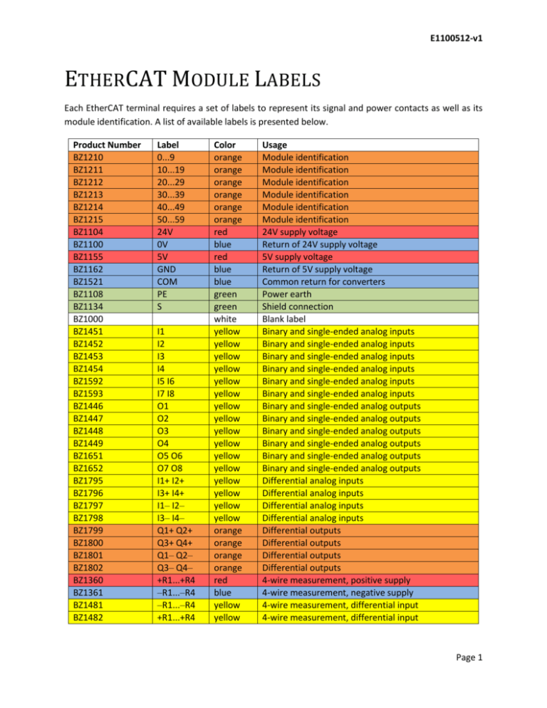
E1100512-v1 ETHERCAT MODULE LABELS Each EtherCAT terminal requires a set of labels to represent its signal and power contacts as well as its module identification. A list of available labels is presented below. Product Number BZ1210 BZ1211 BZ1212 BZ1213 BZ1214 BZ1215 BZ1104 BZ1100 BZ1155 BZ1162 BZ1521 BZ1108 BZ1134 BZ1000 BZ1451 BZ1452 BZ1453 BZ1454 BZ1592 BZ1593 BZ1446 BZ1447 BZ1448 BZ1449 BZ1651 BZ1652 BZ1795 BZ1796 BZ1797 BZ1798 BZ1799 BZ1800 BZ1801 BZ1802 BZ1360 BZ1361 BZ1481 BZ1482 Label 0...9 10...19 20...29 30...39 40...49 50...59 24V 0V 5V GND COM PE S I1 I2 I3 I4 I5 I6 I7 I8 O1 O2 O3 O4 O5 O6 O7 O8 I1+ I2+ I3+ I4+ I1‒ I2‒ I3‒ I4‒ Q1+ Q2+ Q3+ Q4+ Q1‒ Q2‒ Q3‒ Q4‒ +R1...+R4 ‒R1...‒R4 ‒R1...‒R4 +R1...+R4 Color orange orange orange orange orange orange red blue red blue blue green green white yellow yellow yellow yellow yellow yellow yellow yellow yellow yellow yellow yellow yellow yellow yellow yellow orange orange orange orange red blue yellow yellow Usage Module identification Module identification Module identification Module identification Module identification Module identification 24V supply voltage Return of 24V supply voltage 5V supply voltage Return of 5V supply voltage Common return for converters Power earth Shield connection Blank label Binary and single-ended analog inputs Binary and single-ended analog inputs Binary and single-ended analog inputs Binary and single-ended analog inputs Binary and single-ended analog inputs Binary and single-ended analog inputs Binary and single-ended analog outputs Binary and single-ended analog outputs Binary and single-ended analog outputs Binary and single-ended analog outputs Binary and single-ended analog outputs Binary and single-ended analog outputs Differential analog inputs Differential analog inputs Differential analog inputs Differential analog inputs Differential outputs Differential outputs Differential outputs Differential outputs 4-wire measurement, positive supply 4-wire measurement, negative supply 4-wire measurement, differential input 4-wire measurement, differential input Page 1 E1100512-v1 BZ1318 BZ1319 BZ1734 BZ1735 A1 A2 B1 B2 yellow yellow yellow yellow Motor output Motor output Motor output Motor output Figure 1: Available Labels. 1. General A standard EtherCAT module has 10 locations for attaching labels. They are arranged in 2 columns and 5 rows. The top row is used to denote the module number and we only use one location. This leaves 8 locations for marking input, output and power contacts. 0 1 2 3 4 5 6 7 8 Figure 2: Label location on standard EtherCAT module. 2. Module Number We are using an orange number at location 0 to denote the EtherCAT module number, or its position within the stick. This is the same number referenced in the schematics. 3. Signal and Supply Contacts We list each module and its corresponding labels. We mostly follow the examples given in the manual. Some of the communication terminals do not have label positions and stay as they are. Page 2 E1100512-v1 3.1. Coupler: EK1100, EK1101, EK1501 These are usually labeled by the factory. We use the same. # 24V 0V + + ̶ ̶ PE PE Figure 3: Labels for EtherCAT couplers. If the terminal is not labeled, the “+” and “-“ labels should be replaced by the supply voltage labels as is described for the power supply terminal EL9400. 3.2. Extension: EK1110 This terminal has no contacts. Cover empty locations with white or gray blank labels. # Figure 4: Labels for the extension terminal EK1110. Page 3 E1100512-v1 3.3. Power Supply Terminal: EL9400 The power contacts can be used for different voltages. We distinguish 5V supply terminals and 24V supply terminals. # 24V 0V 5V 5V GND GND PE PE Figure 5: Labels for 5V power supply terminal. # 24V 0V 24V 24V 0V 0V PE PE Figure 6: Labels for 24V power supply terminal. Page 4 E1100512-v1 3.4. Feed Terminal: EL9190 The power contacts can be used for different voltages. We distinguish 5V feed terminals and 24V feed terminals. Cover empty locations with white or gray blank labels. # 5V 5V GND GND Figure 7: Labels for 5V power supply terminal. # 24V 24V 0V 0V Figure 8: Labels for 24V power supply terminal. Page 5 E1100512-v1 3.5. Analog Input: EL3102 This terminal has a separate common contact to set the ground voltage of the internal converter. # I1+ I2+ I1‒ I2‒ COM COM S S Figure 9: Labels for the 2-channel 16 bit analog input terminal EL3102. 3.6. Analog Input: EL3104 This terminal does not have a separate common contact to set the ground voltage of the internal converter. The converter ground is provided by the power contact ground (on the side). # I1+ I2+ I1‒ I2‒ I3+ I4+ I3‒ I4‒ Figure 10: Labels for the 4-channel 16 bit analog input terminal EL3104. Page 6 E1100512-v1 3.7. Temperature Input PT100: EL3202-0010 This terminal uses a 4-wire hookup to accurately measure the resistance of a PT100 element. The supply voltage is provided by the red +R and blue –R contacts. The measurement is done between the yellow +R and –R contacts. # +R1 +R2 +R1 +R2 ‒R1 ‒R2 ‒R1 ‒R2 Figure 11: Labels for the 2-channel 16 bit analog input terminal EL3202-0010. 3.8. 4...20mA Analog Input: EL3154 This terminal uses the 24V supply on the power contacts (side) to provide power to the sensors. The current loop is closed through the measurement contacts (Ix). # I1 I2 24V 24V I3 I4 24V 24V Figure 12: Labels for the 4-channel 16 bit 4...20mA analog input terminal EL3154. Page 7 E1100512-v1 3.9. Analog Output: EL4132 This terminal has a common contact that sets the ground voltage of the internal converter and is used as the ground of the signal output. It has to be wired to the ground of the connected device. Cover empty locations with white or gray blank labels. # O1 O2 COM COM S S Figure 13: Labels for the 2-channel 16 bit analog output terminal EL4102. 3.10. Analog Output: EL4134 This terminal does not have a separate common contact. The converter ground is provided by the power contact ground (on the side). The output stages of the converter are powered by the power contact for 24V (on the side). # O1 O2 COM COM O3 O4 COM COM Figure 14: Labels for the 4-channel 16 bit analog output terminal EL4104. Page 8 E1100512-v1 3.11. Digital Input: EL1124 This terminal has to be supplied with 5V through the power feed side contacts. # I1 I2 5V 5V GND GND I3 I4 Figure 15: Labels for the 4-channel TTL digital input terminal EL1124. 3.12. Digital Input: EL1012 This terminal has to be supplied with 24V through the power feed side contacts. # I1 I2 24V 24V GND GND PE PE Figure 16: Labels for the 2-channel TTL digital input terminal EL1012. Page 9 E1100512-v1 3.13. Digital Input: EL1014 This terminal has to be supplied with 24V through the power feed side contacts. # I1 I2 24V 24V 24V 24V I3 I4 Figure 17: Labels for the 4-channel TTL digital input terminal EL1014. 3.14. Digital Input: EL1018 This terminal has to be supplied with 24V through the power feed side contacts. # I1 I2 I3 I4 I5 I6 I7 I8 Figure 18: Labels for the 8-channel TTL digital input terminal EL1018. Page 10 E1100512-v1 3.15. Digital Input: EL1094 This terminal has to be supplied with 24V through the power feed side contacts. # I1 I2 GND GND GND GND I3 I4 Figure 19: Labels for the 4-channel TTL digital input terminal EL1094. 3.16. Digital Input: EL1098 This terminal has to be supplied with 24V through the power feed side contacts. # I1 I2 I3 I4 I5 I6 I7 I8 Figure 20: Labels for the 8-channel TTL digital input terminal EL1098. Page 11 E1100512-v1 3.17. Digital Output: EL2124 This terminal has to be supplied with 5V through the power feed side contacts. # O1 O2 5V 5V GND GND O3 O4 Figure 21: Labels for the 4-channel TTL digital output terminal EL2124. 3.18. Digital Output: EL2002 This terminal has to be supplied with 24V through the power feed side contacts. # O1 O2 24V 24V GND GND PE PE Figure 22: Labels for the 2-channel TTL digital output terminal EL2002. Page 12 E1100512-v1 3.19. Digital Output: EL2004 This terminal has to be supplied with 24V through the power feed side contacts. # O1 O2 GND GND GND GND O3 O4 Figure 23: Labels for the 4-channel TTL digital output terminal EL2004. 3.20. Digital Output: EL2008 This terminal has to be supplied with 24V through the power feed side contacts. # O1 O2 O3 O4 O5 O6 O7 O8 Figure 24: Labels for the 8-channel TTL digital output terminal EL2008. Page 13 E1100512-v1 3.21. Safety Digital Input: EL1904 This terminal has to be supplied with 24V through a power feed terminal. # I1+ I2+ I1‒ I2‒ I3+ I4+ I3‒ I4‒ Figure 25: Labels for the 4-channel safety digital input terminal EL1904. 3.22. Safety Digital Output: EL2904 This terminal has to be supplied with 24V through a power feed terminal. Cover empty locations with white or gray blank labels. # Q1+ Q2+ 24V 24V Q1‒ Q2‒ GND GND Q3+ O4+ Q3‒ Q4‒ Figure 26: Labels for the 4-channel safety digital output terminal EL2904. Page 14 E1100512-v1 3.23. Safety PLC Terminal: EL6900 This terminal has no contacts. Cover empty locations with white or gray blank labels. # Figure 27: Labels for the safety PLC terminal EL6900. 3.24. Memory Terminal: EL6080 This terminal has no contacts. Cover empty locations with white or gray blank labels. # Figure 28: Labels for the memory terminal EL6080. Page 15 E1100512-v1 3.25. Motor Terminal: EL7332 This terminal requires a 24V supply. # A1 A2 B1 B2 24V 0V I1 I2 Figure 29: Labels for the motor terminal EL7332. Page 16
