op2.8
advertisement
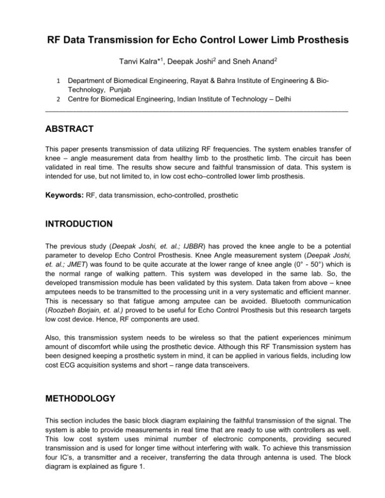
RF Data Transmission for Echo Control Lower Limb Prosthesis Tanvi Kalra*1, Deepak Joshi2 and Sneh Anand2 1 Department of Biomedical Engineering, Rayat & Bahra Institute of Engineering & BioTechnology, Punjab 2 Centre for Biomedical Engineering, Indian Institute of Technology – Delhi ________________________________________________________________________________________ ABSTRACT This paper presents transmission of data utilizing RF frequencies. The system enables transfer of knee – angle measurement data from healthy limb to the prosthetic limb. The circuit has been validated in real time. The results show secure and faithful transmission of data. This system is intended for use, but not limited to, in low cost echo–controlled lower limb prosthesis. Keywords: RF, data transmission, echo-controlled, prosthetic INTRODUCTION The previous study (Deepak Joshi, et. al.; IJBBR) has proved the knee angle to be a potential parameter to develop Echo Control Prosthesis. Knee Angle measurement system (Deepak Joshi, et. al.; JMET) was found to be quite accurate at the lower range of knee angle (0° - 50°) which is the normal range of walking pattern. This system was developed in the same lab. So, the developed transmission module has been validated by this system. Data taken from above – knee amputees needs to be transmitted to the processing unit in a very systematic and efficient manner. This is necessary so that fatigue among amputee can be avoided. Bluetooth communication (Roozbeh Borjain, et. al.) proved to be useful for Echo Control Prosthesis but this research targets low cost device. Hence, RF components are used. Also, this transmission system needs to be wireless so that the patient experiences minimum amount of discomfort while using the prosthetic device. Although this RF Transmission system has been designed keeping a prosthetic system in mind, it can be applied in various fields, including low cost ECG acquisition systems and short – range data transceivers. METHODOLOGY This section includes the basic block diagram explaining the faithful transmission of the signal. The system is able to provide measurements in real time that are ready to use with controllers as well. This low cost system uses minimal number of electronic components, providing secured transmission and is used for longer time without interfering with walk. To achieve this transmission four IC’s, a transmitter and a receiver, transferring the data through antenna is used. The block diagram is explained as figure 1. KNEE-ANGLE from measurement system ENCODER ADC TRANSMITTER ANTENNA DAC DECODER RECIEVER Figure 1: BLOCK DIAGRAM OF THE SYSTEM The above block diagram includes two parts:(a) Transmitter circuit – this circuit helps in the secured transmission of the data through the antenna. The section covers three blocks which are as follows: 1. ADC- the IC used for the conversion of analog signal to the digital values is ADC 0804. It is a 20 pin IC that has 8 data pins. The 8 bit data (D0-D7) from these pins is sent to the encoder. 2. Encoder- it takes up the 8 bit data from ADC and then encodes this parallel data (D0-D7) into serial data. The IC used is HT 640(24 pin). The serial data from its DATA OUT pin is send to the transmitter. 3. Transmitter- the TWS-434 module is extremely small. The transmitter module is only 1/3 the size of a standard postage stamp, and can easily be placed inside a small plastic enclosure. The transmitter output is up to 8mW at 433.92MHz. It accepts both linear and digital inputs and can operate from 1.5 to 12 Volts-DC, and makes building a miniature hand-held RF transmitter very easy. It takes up the data from the encoder and then the wireless transmission is done through ANTENNA. (b) Receiver circuit – this circuit does the faithful reception of the data through the antenna at the receiver end. This section also includes three blocks which are as follows: 1. Receiver- RWS-434 is also extremely small. The receiver also operates at 433.92MHz, and has a sensitivity of 3uV. The receiver operates from 4.5 to 5.5 volts-DC, and has both linear and digital outputs. It receives the data through its ANTENNA and then send it to decoder. 2. Decoder- it takes up the serial data from the receiver’s DATA pin and decodes it into parallel 8 bit data. The IC used is HT 648(24 pin). Its parallel data is then send to DAC through 8 data pins (D0-D7). 3. DAC- It is a 16 pin IC which takes 8 bit data from decoder. The IC used for the conversion of digital signal back into analog form is DAC 0800. This analog data is then send to IC 741(8 pin) which act as current to voltage converter. TRANSMITTER AND RECIEVER MODULE The TWS-434 and RWS-434 are extremely small as shown in Figure 2 & 3. The transmitter and receiver modules are excellent for applications requiring short-range RF remote controls. For maximum range, the recommended antenna in approximately 35cm long. TWS-434 & RWS-434 RF modules are used for serial communication. The pin diagram of both the modules is shown in Figure 4 & 5. Figure 2: TRANSMITTER MODULE Figure 4: TWS-434 Pin Diagram Figure 3: RECIEVER MODULE Figure 5: RWS-434 Pin Diagram RESULTS AND DISCUSSION The knee - angle measurement system which was developed earlier as shown in Figure 6 is used as source of data. The signal from this system was transferred wirelessly using the constructed module. After all the connections have been made the observed waveforms at CRO show faithful data transmission at different values of knee angle. The snapshots in Figure 7 shows two channels, channel 1 shows output at transmitter end and channel 2 shows output at the receiver end. As the knee angle changes at the transmitter end the same change is observed at the receiver end. The simultaneous change is perfectly indicated in the figures. Figure 6: Knee-Angle Measurement System (developed in lab, CBME, IITD) (a) (b) (c) (d) (e) Figure 7(a)-(e): These snap shots shows the orderly change in the data at both the ends (channel 1- transmitter end, channel 2 - receiver end) CONCLUSION Thus, it can be concluded that by using the above developed schematic, signal can be transmitted. Hence this system shows its direct application in the Echo Control Lower Limb Prosthesis. Apart from this, the developed module has direct application in other wireless medical devices. Implementation & interfacing of this module in real time operating prosthesis is under progress. REFERENCES Deepak Joshi, Sneh Anand. Study of circular cross correlation and phase lag to estimate knee angle: an application to prosthesis; Int. J. Biomechatronics and Biomedical Robotics [in press] Roozbeh Borjain, Mir Behrad Khamesee, William Melek. Feasibility study on echo control of a prosthetic knee: sensor and wireless communication; Microsyst Technol, Vol.16, No.257-265 [2010] Deepak Joshi et.al. kinematics-coordinated walking pattern based on embedded controls; journal of medical engineering & technology [in press] http://www.rentron.com/rf_remote_control.htm http://pdf1.alldatasheet.com/datasheet-pdf/view/82103/HOLTEK/HT640.html http://pdf1.alldatasheet.com/datasheet-pdf/view/64465/HOLTEK/HT648L.html ________________________________________________________________________________________ * Corresponding Author E-mail address: kalra.tanvi@gmail.com

