generator 1
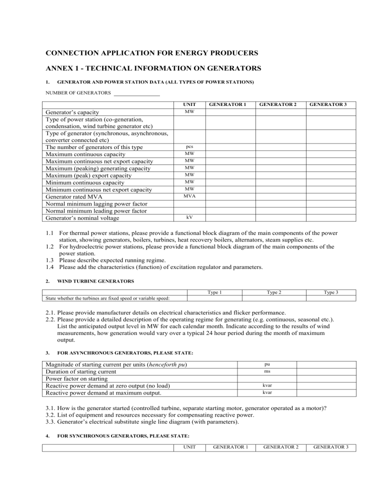
CONNECTION APPLICATION FOR ENERGY PRODUCERS
ANNEX 1 - TECHNICAL INFORMATION ON GENERATORS
1.
GENERATOR AND POWER STATION DATA (ALL TYPES OF POWER STATIONS)
NUMBER OF GENERATORS
UNIT GENERATOR 1
Generator’s capacity MW
Type of power station (co-generation, condensation, wind turbine generator etc)
Type of generator (synchronous, asynchronous, converter connected etc)
The number of generators of this type
Maximum continuous capacity pcs
MW
Maximum continuous net export capacity
Maximum (peaking) generating capacity
MW
MW
Maximum (peak) export capacity
Minimum continuous capacity
MW
MW
Minimum continuous net export capacity
Generator rated MVA
MW
MVA
Normal minimum lagging power factor
Normal minimum leading power factor
Generator’s nominal voltage kV
GENERATOR 2 pu ms kvar kvar
GENERATOR 3
1.1
For thermal power stations, please provide a functional block diagram of the main components of the power station, showing generators, boilers, turbines, heat recovery boilers, alternators, steam supplies etc.
1.2
For hydroelectric power stations, please provide a functional block diagram of the main components of the power station.
1.3
Please describe expected running regime.
1.4
Please add the characteristics (function) of excitation regulator and parameters.
2.
WIND TURBINE GENERATORS
State whether the turbines are fixed speed or variable speed:
Type 1 Type 2 Type 3
2.1.
Please provide manufacturer details on electrical characteristics and flicker performance.
2.2.
Please provide a detailed description of the operating regime for generating (e.g. continuous, seasonal etc.).
List the anticipated output level in MW for each calendar month. Indicate according to the results of wind measurements, how generation would vary over a typical 24 hour period during the month of maximum output.
3.
FOR ASYNCHRONOUS GENERATORS, PLEASE STATE:
Magnitude of starting current per units ( henceforth pu )
Duration of starting current
Power factor on starting
Reactive power demand at zero output (no load)
Reactive power demand at maximum output.
3.1.
How is the generator started (controlled turbine, separate starting motor, generator operated as a motor)?
3.2.
List of equipment and resources necessary for compensating reactive power.
3.3.
Generator’s electrical substitute single line diagram (with parameters).
4.
FOR SYNCHRONOUS GENERATORS, PLEASE STATE:
UNIT GENERATOR 1 GENERATOR 2 GENERATOR 3
Generator direct axis transient reactance
(saturated)
Generator direct axis sub-transient reactance
(saturated)
Negative phase sequence reactance pu pu
Zero sequence reactance
5.
GENERATOR DATA FOR FAULT STUDIES (ALL PLANT TYPES)
UNIT GENERATOR 1 pu Generator direct axis positive phase sequence synchronous reactance*
Generator quadrature axis positive phase sequence synchronous reactance* pu pu Generator direct axis transient reactance
(unsaturated)*
Generator quadrature axis transient reactance
(unsaturated)* pu
Generator sub-transient reactance
(unsaturated)* pu pu Direct axis transient open circuit, time constant*
Direct axis sub-transient open circuit, time constant* pu pu Quadrature axis transient open circuit, time constant*
Quadrature axis sub-transient open circuit, time constant* pu
Inertia of complete turbo generator
Generator direct axis positive phase sequence
Kgm
2 s synchronous reactance
* completed for all synchronous generators
6.
GENERATOR TRANSFORMER DATA
Number of transformers at the network connection point
Unit generator transformer rated MVA
Unit generator transformer voltage ratio HV/LV
Unit generator transformer % impedance
Unit
MVA
%
7.
POWER STATION DATA
Unit
Maximum consumption capacity at starting MVA
Auxilliary system maximum consumption MW
8.
DESCRIPTION OF AUXILLIARY SYSTEM CONNECTION
Generator 1
GENERATOR 2 GENERATOR 3
Generator 2 Generator 3
