3 PHASE SECONDARY ENERGY METER
advertisement
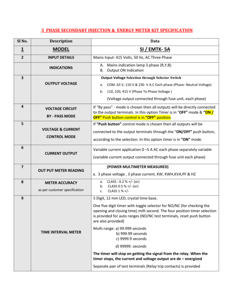
3 PHASE SECONDARY INJECTION & ENERGY METER KIT SPECIFICATION Sl No. Description Data 1 MODEL SI / EMTK- 5A 2 INPUT DETAILS INDICATIONS Mains Input: 415 Volts, 50 Hz, AC Three Phase A. Mains indication lamp 3 phase (R,Y,B) B. Output ON Indication Output Voltage Selection through Selector Switch 3 OUTPUT VOLTAGE a. COM. 63 V, 110 V & 230 V A.C Each phase (Phase- Neutral Voltage) b. 110, 220, 415 V (Phase To Phase Voltage ) (Voltage output connected through fuse unit, each phase) 4 VOLTAGE CIRCUIT BY - PASS MODE 5 If “Push button” control mode is chosen then all outputs will be VOLTAGE & CURRENT CONTROL MODE 6 CURRENT OUTPUT 7 8 If “By pass” - mode is chosen then all outputs will be directly connected to the output terminals. In this option Timer is in “OFF” mode & “ON / OFF” Push button control is in “OFF” position. OUT PUT METER READING METER ACCURACY as per customer specification 9 connected to the output terminals through the “ON/OFF” push button, according to the selection. In this option timer is in “ON” mode. Variable current application 0 –5 A AC each phase separately variable (variable current output connected through fuse unit each phase) (POWER MULTIMETER MEASURED) a. 3 phase voltage , 3 phase current, KW, KWH,KVA,PF & HZ a. b. c. CLASS : 0.2 % +/- (or) CLASS 0.5 % +/- (or) CLASS 1 % +/- 5 Digit, 12 mm LED, crystal time base. One five digit timer with toggle selector for NO/NC (for checking the opening and closing time) milli second. The four position timer selection is provided for auto ranges (NO/NC test terminals, reset push button are also provided) TIME INTERVAL METER Multi-range: a) 99.999 seconds b) 999.99 seconds c) 9999.9 seconds d) 99999. seconds The timer will stop on getting the signal from the relay. When the timer stops, the current and voltage output are de – energized Separate pair of test terminals (Relay trip contacts) is provided 9 CONSTRUCTION 10 PANEL COMPRISING OF 11 DIMENSIONS 12 WEIGHT 13 STANDARD ACCESSORIES :- Powder coated MS Box with Carrying handle. 1. 2. 3. 4. 5. 6. 7. 8. 9. Mains ON/OFF MCB Control (Input) Push Button Control Output ON/ OFF & Timer Reset Input Terminals R,Y,B & N Phase Shifter Input Terminals R,Y,B & N Phase Shifter Out put Terminals R,Y,B & N Timer Test Terminals By pass / Control Selector Switch Timer NO/ NC Selector Switch Fuse Protection for all Output Voltage and Output Current W x D x H: 17.5” x 13” x 9” approx. 26 kgs Approx. 1. Test Cable 2 Meters long with Crocodile Clip : 1 No. (6 Core Current Cable) 2. Test Cable 2 Meters long with Crocodile Clip : 1 No. (4 Core AC Voltage Cable) 3. Test Cable (Timer) 2 Meters long with Crocodile Clip : 1 Set 4. Mains Card 2 Meter : 1 Nos. (4 Core AC Voltage Cable) 5. Spare Fuse 5 A (Main Fuse ) – 10 Nos. 6. Spare Fuse 300mA (Main Fuse ) – 10 Nos. 7. Instruction Manual – 1 No. 8. Calibration Certificate – 1 No. 9. Carrying bag – 1 No.
