PMD interface
advertisement
114 Physical Coding Sublayer (PCS), Physical Medium Attachment (PMA), type
1000BASE-H
Interface to the PMD
The interface between the PCS and the PMD is defined in terms of signals for which no
specific implementation is described.
Signals transmitted to the PMD
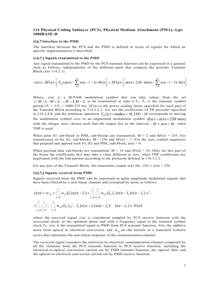
Any signal transmitted to the PMD by the PCS transmit function can be expressed in a general
form as follows, independently of the different parts that compose the periodic Transmit
Block (see 114.2.1).
Nb
Nb
æ
ö
æ
ö
x(n) = SF(n)× ç FM (a(n) - å x(n - i -1)×b(i))÷ = SF(n)× ç a(n) + 2M × m(n) - å x(n - i -1)×b(i)÷
è
ø
è
ø
i=0
i=0
Where, a(n) is a M-PAM modulation symbol that can take values from the set
{-M +1, -M + 3, , M - 3, M -1} to be transmitted at time n·T s , T s is the transmit symbol
period (T s = 1/F s = 1000/325 ns), SF(n) is the power scaling factor specified for each part of
the Transmit Block according to 114.2.2.1, b(i) are the coefficients of TH precoder specified
in 114.2.4.8, and the nonlinear operation FM (a ) = mod(a + M, 2M) - M corresponds to moving
the modulation symbol a(n) to an augmented modulation symbol a(n) = a(n) + 2M·m(n)
with the integer m(n) chosen such that the output lies in the interval -M £ x(n) < M , when
THP is used.
When pilot S1 sub-block or PHS x sub-blocks are transmitted, M = 2 and SF(n) = 255. For
transmission of the S2 x sub-blocks, M = 256 and SF(n) = 1. For the zero symbol sequences
that prepend and append each S1, S2 and PHS x sub-block, a(n) = 0.
When payload data sub-blocks are transmitted, M = 16 and SF(n) = 16. Only for this part of
the frame the coefficients b(i) may take a value different to zero, when THP coefficients are
negotiated with the link partner according to the protocols defined in 114.3.2.2.
For any part of the Transmit Block, the transmitter output x(n) fits -256 ≤ x(n) < 256.
Signals received from PMD
Signals received from the PMD can be expressed as pulse -amplitude modulated signals that
have been filtered by a non-linear channel and corrupted by noise as follows:
L
L
L
y(n) = wo0 + å wo1 (l1 )x(n - l1 ) + å å wo2 (l1, l2 )x(n - l1 )x(n - l2 ) +…
l1 =0
L
L
+ å å…
l1 =0 l2 =0
L
åw
oP
l1 =0 l2 =0
(l1, l2 ,… lP )x(n - l1 )x(n - l2 )… x(n - lP ) + N(n)
l p =0
where the received signal y(n) is considered sampled by PCS receive function with the
recovered clock, at the optimum phase and with a frequency equal to the transmit symbol
clock Fs. x(n) is the transmitted signal to PMD from PCS transmit function, N(n) the additive
noise from optical to electrical conversion, and wox are the kernels of a truncated Volterra
series that represents the non-linear response of the communication channel.
The received signal considers the electrical-to-electrical communication channel composed by
all the elements from the PCS transmit function to PCS receive function, including the
electrical-to-optical conversion carried out by PMD transmit function, the optical fiber and
the optical-to-electrical conversion carried out by PMD receive function.
1
