Design Report - New Mexico Office of the State Engineer
advertisement
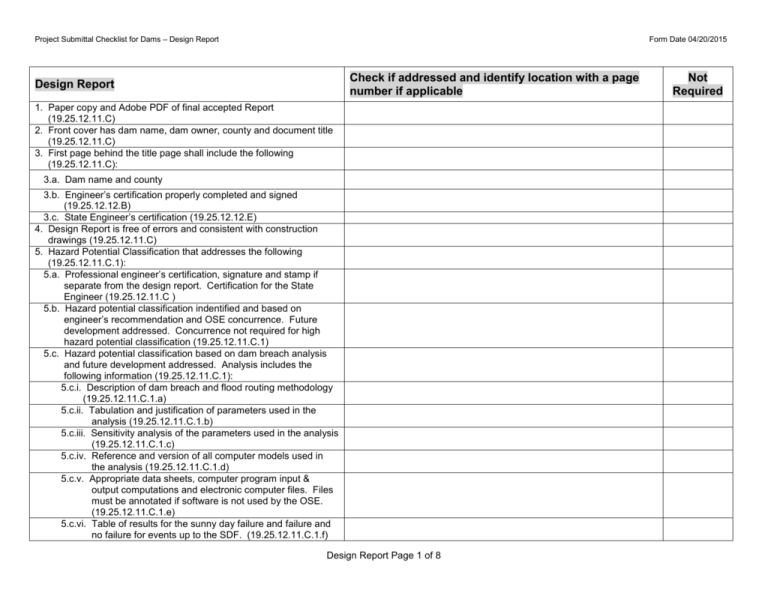
Project Submittal Checklist for Dams – Design Report Form Date 04/20/2015 Check if addressed and identify location with a page number if applicable Design Report 1. Paper copy and Adobe PDF of final accepted Report (19.25.12.11.C) 2. Front cover has dam name, dam owner, county and document title (19.25.12.11.C) 3. First page behind the title page shall include the following (19.25.12.11.C): 3.a. Dam name and county 3.b. Engineer’s certification properly completed and signed (19.25.12.12.B) 3.c. State Engineer’s certification (19.25.12.12.E) 4. Design Report is free of errors and consistent with construction drawings (19.25.12.11.C) 5. Hazard Potential Classification that addresses the following (19.25.12.11.C.1): 5.a. Professional engineer’s certification, signature and stamp if separate from the design report. Certification for the State Engineer (19.25.12.11.C ) 5.b. Hazard potential classification indentified and based on engineer’s recommendation and OSE concurrence. Future development addressed. Concurrence not required for high hazard potential classification (19.25.12.11.C.1) 5.c. Hazard potential classification based on dam breach analysis and future development addressed. Analysis includes the following information (19.25.12.11.C.1): 5.c.i. Description of dam breach and flood routing methodology (19.25.12.11.C.1.a) 5.c.ii. Tabulation and justification of parameters used in the analysis (19.25.12.11.C.1.b) 5.c.iii. Sensitivity analysis of the parameters used in the analysis (19.25.12.11.C.1.c) 5.c.iv. Reference and version of all computer models used in the analysis (19.25.12.11.C.1.d) 5.c.v. Appropriate data sheets, computer program input & output computations and electronic computer files. Files must be annotated if software is not used by the OSE. (19.25.12.11.C.1.e) 5.c.vi. Table of results for the sunny day failure and failure and no failure for events up to the SDF. (19.25.12.11.C.1.f) Design Report Page 1 of 8 Not Required Project Submittal Checklist for Dams – Design Report Form Date 04/20/2015 5.c.vii. Inundation maps for the sunny day failure and SDF (19.25.12.11.C.1.g) 6. Hydrologic Analysis that addresses the following (19.25.12.11.C.2): 6.a. Professional engineer’s certification, signature and stamp if separate from the design report. Certification for the State Engineer (19.25.12.11.C ) 6.b. Topographic map of the drainage area (19.25.12.11.C.2.a) 6.c. Description of topography, soils, vegetative cover and land treatment, if proposed (19.25.12.11.C.2.b) 6.d. Design storm depth, duration and distribution discussed and justified (19.25.12.11.C.2.c) 6.e. Discussion of methodology of converting rainfall to runoff independent of the software program used in the analysis (19.25.12.11.C.2.d) 6.f. Discussion, justification and tabulation of all model input parameters independent of the software program used in the analysis (19.25.12.11.C.2.d) 6.g. Table of reservoir area and storage capacity for each foot of elevation referenced to NAVD 88. Indicate elevation of outlet invert, spillway(s) and dam crest (19.25.12.11.C.2.g) 6.h. Outlet and spillway rating tables including calculations (19.25.12.11.C.5) 6.i. Plot of inflow and outflow hydrographs on the same figure (19.25.12.11.C.2.f) 6.j. Discussion of results including peak inflow, volume of runoff, and max. reservoir level of routed hydrograph, outflow hydrograph, etc. (19.25.12.11.C.2.e) 6.k. Computer input and output files provided including a digital copy. Files must be annotated if software is not used by the OSE. (19.25.12.11.C.2.h) 7. Passes or contains Spillway Design Flood (SDF) (19.25.12.11.C.3) 8. Incremental Damage Assessment if SDF criteria not met and assessment addresses the following (19.25.12.11.C.4): 8.a. Assessment compares flood routing with dam failure and without dam failure. Items under Checklist 5.c addressed. 8.b. Criteria for determining incremental damage documented 8.c. Incremental damage assessment supports reduced SDF 9. Spillway rating curve and table from spillway crest to dam crest and the following supporting information (19.25.12.11.C.5): Design Report Page 2 of 8 Project Submittal Checklist for Dams – Design Report Form Date 04/20/2015 9.a. Justification of parameters used to determine spillway capacity 9.b. Annotated computer input and output files provided including a digital copy 10. Spillway Design that addresses the following (19.25.12.11.C.6): 10.a. Spillway lining and erosion potential addressed (19.25.12.11.C.6.a) 10.b. Cavitation addressed on control weirs (19.25.12.11.C.6.b) 10.c. Discharge away from the downstream toe and abutment slopes (19.25.12.11.C.6.c) 10.d. Accumulation of debris addressed (19.25.12.11.C.6.d) 10.e. Energy dissipation addressed (19.25.12.11.C.6.e) 10.f. Channel lining addresses erosion, joints, displacement, water stops, etc. (19.25.12.11.C.6.f) 10.g. Adequate design of training dike (19.25.12.11.C.6.g) 11. Outlet Works Capacity including the following information (19.25.12.11.C.7) 11.a. Hydraulic calculations documented including justification of assumptions (19.25.12.11.C.7) 11.b. Stage/discharge rating curve and table in 1-foot increments from invert to dam crest (19.25.12.11.C.7) 11.c. Reservoir drains in 45 days for water storage or 96 hours for flood control dam (unless waiver is approved by Water Rights District Office) (19.25.12.11.C.7. a or b.) 11.d. Annotated computer input and output files provided including a digital copy (19.25.12.11.C.7) 12. Outlet Works Design including the following information (19.25.12.11.C.8): 12.a. Conduit diameter greater than or equal to 18 inches (19.25.12.11.C.8.a) 12.b. Appropriate use of metal conduits (19.25.12.11.C.8.b) 12.c. Gate located at upstream end or includes guard gate or bulkhead (19.25.12.11.C.8.c) 12.d. Conduit adequately vented with supporting calculations (19.25.12.11.C.8.d) 12.e. Conduit by-pass valve if conduit ties to a downstream pipe – note exception if adequate access (19.25.12.11.C.8.d) 12.f. Outlet operators designed to prevent damage from vandalism, weather, ice, floating debris, wave action, settlement, etc. (19.25.12.11.C.8.e) Design Report Page 3 of 8 Project Submittal Checklist for Dams – Design Report Form Date 04/20/2015 12.g. Outlet operators accessible during outlet and spillway releases (19.25.12.11.C.8.e) 12.h. Flood control dams have ungated outlet conduit (19.25.12.11.C.8.f) 12.i. Trash racks on intake structure with appropriate grate openings (19.25.12.11.C.8.g) 12.j. Energy dissipation addressed at terminal structure (19.25.12.11.C.8.h) 12.k. Structural design calculations for all loading conditions (19.25.12.11.C.8.i) 12.l. Watertight joints and fittings for the conduit (19.25.12.11.C.8.j) 12.m. Conduit on stable foundation with settlement analysis if necessary (19.25.12.11.C.8.k) 12.n. Seepage and compaction along the conduit addressed (19.25.12.11.C.8.l) 12.o. Structural design calculations for intake, conduit and terminal structure provided (19.25.12.11.C.8.m) 13. Geologic Assessment for high and significant hazard dam including the following (19.25.12.11.C.9): 13.a. Professional engineer’s certification, signature and stamp if separate from the design report. Certification for the State Engineer (19.25.12.11.C ) 13.b. Regional geologic setting, local and site geology 13.c. Geologic suitability of the dam foundation 13.d. Slide potential of the reservoir rim and abutment areas 13.e. Seismic history and potential 14. Geotechnical Investigation including the following information (19.25.12.11.C.10): 14.a. Professional engineer’s certification, signature and stamp if separate from the design report. Certification for State Engineer (19.25.12.11.C ) 14.b. Test borings in footprint of dam, spillway and other appurtenant structures (19.25.12.11.C.10.a) 14.c. SPT or other field testing to assess soil character and consistency (19.25.12.11.C.10.b) 14.d. Undisturbed sampling for density, shear strength and compressibility tests (19.25.12.11.C.10.c) 14.e. Measurement of water level in drill holes and elevations provided (19.25.12.11.C.10.e) Design Report Page 4 of 8 Project Submittal Checklist for Dams – Design Report Form Date 04/20/2015 14.f. Field permeability testing if necessary (19.25.12.11.C.10.f) 14.g. Logs of test borings and test pits, location map and profile along dam axis (19.25.12.11.C.10.g) 14.h. Testing of construction materials to determine shear strength, permeability, compressibility and filter characteristics (19.25.12.11.C.10.h) 14.i. Evaluation of liquefaction potential (19.25.12.11.C.10.i) 14.j. Evaluation of dynamic shear strength if deformation analysis required (19.25.12.11.C.10.i) 14.k. Location of the borrow material and borrow stock piles identified (19.25.12.11.C.10.j) 14.l. Other supplemental tests (19.25.12.11.C.10.d) 14.m. Parameters to be used in the design recommended 15. Seepage Analysis for high and significant hazard including the following information(19.25.12.11.C.11): 15.a. Waiver request for flood control dams that drain in 96 hours (19.25.12.11.C.11) 15.b. Discussion of methodology independent of the software program used in the analysis 15.c. Discussion, justification and tabulation of all model input parameters independent of the software program used in the analysis 15.d. Flow nets of appropriate size and scale (19.25.12.11.C.11.a) 15.e. Annotated computer input and output files provided including an electronic copy of the model(19.25.12.11.C.11.a) 15.f. Adequate design of filter, transition and drainage zones; thickness greater than or equal to 3 feet (19.25.12.11.C.11.b) 15.g. Exit seepage gradient acceptable (19.25.12.11.C.11.b) 15.h. Drain pipes made of non-corrodible material (19.25.12.11.C.11.c) 15.i. Drain pipes enveloped in properly designed filter material (19.25.12.11.C.11.c) 15.j. Perforation size is acceptable (19.25.12.11.C.11.c) 15.k. Drain and collector pipes designed to flow depth <1/4 diameter (19.25.12.11.C.11.d) 15.l. Drain diameter greater than or equal to 6 inches (19.25.12.11.C.11.d) 15.m. Drain pipes isolated to allow flow measurement of each pipe (19.25.12.11.C.11.d) Design Report Page 5 of 8 Project Submittal Checklist for Dams – Design Report Form Date 04/20/2015 15.n. Measuring device appropriate for the rate of flow (19.25.12.11.C.11.d) 15.o. Measuring device equipped with sediment trap (19.25.12.11.C.11.d) 15.p. Rodent screens provided if discharging to daylight (19.25.12.11.C.11.d) 16. Stability Analysis including the following information (19.25.12.11.C.12): 16.a. Low hazard dam with U.S. slope 3H to 1 V; D.S. slope 2H to 1V and Height 25 ft., analysis not required (19.25.12.11.C.12) 16.b. Model adequately represents the proposed dam 16.c. Discussion of methodology independent of the software program used in the analysis 16.d. Discussion, justification and tabulation of all model input parameters independent of the software program used in the analysis 16.e. Scaled drawing with critical failure plane identified 16.f. Factor of safety for steady state long-term stability 1.5 (19.25.12.11.C.12.a) 16.g. Factor of safety for operational drawdown, 1.5 (19.25.12.11.C.12.b) 16.h. Factor of safety for rapid drawdown 1.3 (19.25.12.11.C.12.c) 16.i. Factor of safety for end of construction 1.3 (19.25.12.11.C.12.d) 16.j. Stability of reservoir rim for slopes steeper than 3h to 1V 16.k. Annotated computer input and output files provided including an electronic copy of the model 17. Seismic Analysis for high and significant hazard dams (19.25.12.11.C.13) 17.a. Seismological investigation including justification of the seismic parameters for the earthquake of appropriate frequency or MCE (19.25.12.11.C.13.a) 17.b. Potential for liquefaction or sliding addressed for the foundation, abutments, embankment and reservoir area (19.25.12.11.C.13.b) 17.c. Conditions met for pseudostatic analysis (19.25.12.11.C.13.c) 17.d. Factor of safety for pseudostatic condition, 1.1 (19.25.12.11.C.13.c) Design Report Page 6 of 8 Project Submittal Checklist for Dams – Design Report Form Date 04/20/2015 17.e. If deformation analysis performed, freeboard 3 feet after deformation (19.25.12.11.C.13.d) 17.f. If deformation analysis performed, justification and tabulations of all input parameters, annotated computer input and output files including a digital copy 17.g. Appurtenant structures stable under seismic analysis 18. Dam Geometry (19.25.12.11.C.14) 18.a. Adequate crest width, H/5 + 8 (19.25.12.11.C.14.a) 18.b. Appropriate surfacing for road on dam crest (19.25.12.11.C.14.b) 18.c. Cover above clay core 2 feet (19.25.12.11.C.14.c) 18.d. Turnarounds on dam crest, as needed (19.25.12.11.C.14.d) 18.e. Crest graded to prevent ponding (19.25.12.11.C.14.e) 18.f. Slopes with adequate erosion protection from crest drainage (19.25.12.11.C.14.f) 18.g. Concentrated crest drainage discharged to prevent embankment erosion (19.25.12.11.C.14.h) 18.h. Adequate camber supported by embankment settlement analysis (19.25.12.11.C.14.g) 19. Freeboard (minimum of 4 feet) (19.25.12.11.C.15) 19.a. Wave runup from 100 mph wind w/ w.l. at spillway crest (19.25.12.11.C.15.a) 19.b. Wave runup from 50 mph wind w/ w.l. at max. reservoir level (19.25.12.11.C.15.b) 19.c. Minimum 3 feet remain after seismic deformation analysis, if required (19.25.12.11.C.15.d) 20. Erosion protection (19.25.12.11.C.16) 20.a. Wave erosion protection waived for flood control dams that drain in 96 hours (19.25.12.11.C.16.a) 20.b. Wave erosion protection. Riprap and filter design is documented and provides adequate coverage (19.25.12.11.C.16.a) 20.c. Area of erosion protection adequate (19.25.12.11.C.16.a) 20.d. Surface erosion protection for crest, slopes, abutments, toe area, etc. (19.25.12.11.C.16.b) 21. Geotextile Design (19.25.12.11.C.17) 21.a. Location of use is appropriate 21.b. Used in accordance with manufacturer’s recommendations and specifications Design Report Page 7 of 8 Project Submittal Checklist for Dams – Design Report Form Date 04/20/2015 21.c. Design computation provided 22. Structural Design (19.25.12.11.C.18) 22.a. Structural design calculations for all appurtenant structures including appropriate loading conditions (water, earth, ice, etc.) 22.b. Reinforced concrete design calculations provided including appropriate loading conditions 22.c. Computer input and output computations provided 23. Utility placement or relocation addressed (19.25.12.11.C.18) 23.a. Utility relocation addressed within embankment, spillway and seepage footprint 23.b. Utilities remaining satisfy provisions for outlet conduits (compaction & seepage) 24. Other Design considerations (19.25.12.11.C.20) Design Report Page 8 of 8
