Autopatcher User`s Manual
advertisement
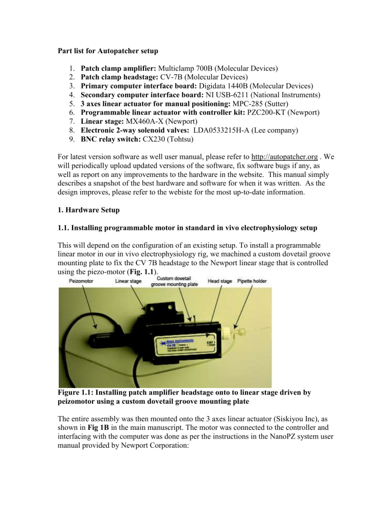
Part list for Autopatcher setup 1. 2. 3. 4. 5. 6. 7. 8. 9. Patch clamp amplifier: Multiclamp 700B (Molecular Devices) Patch clamp headstage: CV-7B (Molecular Devices) Primary computer interface board: Digidata 1440B (Molecular Devices) Secondary computer interface board: NI USB-6211 (National Instruments) 3 axes linear actuator for manual positioning: MPC-285 (Sutter) Programmable linear actuator with controller kit: PZC200-KT (Newport) Linear stage: MX460A-X (Newport) Electronic 2-way solenoid valves: LDA0533215H-A (Lee company) BNC relay switch: CX230 (Tohtsu) For latest version software as well user manual, please refer to http://autopatcher.org . We will periodically upload updated versions of the software, fix software bugs if any, as well as report on any improvements to the hardware in the website. This manual simply describes a snapshot of the best hardware and software for when it was written. As the design improves, please refer to the webiste for the most up-to-date information. 1. Hardware Setup 1.1. Installing programmable motor in standard in vivo electrophysiology setup This will depend on the configuration of an existing setup. To install a programmable linear motor in our in vivo electrophysiology rig, we machined a custom dovetail groove mounting plate to fix the CV 7B headstage to the Newport linear stage that is controlled using the piezo-motor (Fig. 1.1). Figure 1.1: Installing patch amplifier headstage onto to linear stage driven by peizomotor using a custom dovetail groove mounting plate The entire assembly was then mounted onto the 3 axes linear actuator (Siskiyou Inc), as shown in Fig 1B in the main manuscript. The motor was connected to the controller and interfacing with the computer was done as per the instructions in the NanoPZ system user manual provided by Newport Corporation: ftp://download.newport.com/MotionControl/Current/MotionControllers/PZC200/Manual/ NanoPZ.pdf 1.2. Installing programmable pressure control valves The circuit diagram for actuation of the solenoid valves is shown in Fig. 1.2. Instructions to make pneumatic connections are shown in Supplementary Fig. 1 of the paper, and described below: Analog out 1 Analog out 2 Valve 1 Analog out 3 Valve 2 Valve 3 5 VDC MOSFET 1 MOSFET 2 MOSFET 3 Figure 1.2: Circuit diagram for controlling soleniod valves for pressure modulation Any MOSFET that can deliver ~0.16 A of current to a solenoid valve, can be used. The power supply will need to be able to supply a total of ~0.5A, for the three MOSFETS used to operate the three valves. We typically use the Fairchild BS170 MOSFET (Part # 512-BS170D26Z). We use a benchtop power supply (e.g., from Agilent) for powering the circuit. 1) Connect the Common port (output) of Valve 1 to pipette holder. 2) Connect the Common port (output) of Valve 2 to normally open (N.O.) input port of Valve 1. 3) Connect the Common port (output) of Valve 3 to normally closed (N.C.) input port of Valve 1. For port locations, see the mechanical drawing of the soleniod valves: http://www.theleeco.com/PDF.nsf/2355f3df133a527185256c9300562a42/e8bb4dc1b62a 5f54852569a6006b64d8/$FILE/LHDA0030000BA.pdf For computer control of the bank of valves, 1) Connect Digital Out 0 (AO0) of the USB 6211 to the gate of MOSFET 1 to drive Valve 1. 2) Connect Digital Out 1 (AO1) of the USB 6211 to the gate of MOSFET 2 to drive Valve 2. 3) Connect Digital Out 2 (AO2) of the USB 6211 to the gate of MOSFET 3 to drive Valve 3. 4) Connect Digital Out 3 (DO3) of the USB 6211 to the gate of MOSFET 4 to drive the BNC relay. 1.3. Interfacing Amplifier to computer The signals for the Multiclamp 700B amplifier (Molecular Devices) are sent to and from two computer interface boards. The NIDAQ USB-6211 (National instruments) board is used to send signals to the amplifier during Autopatcher operation, and the Digidata 1440A is used for recording with commercial software Pclamp (Molecular Devices) once whole cell is obtained. For this dual interface: 1) Connect Analog Out 0 (AO0) of the NIDAQ USB-6211 to the channel A of the BNC relay switch. 2) Connect the Analog out 0 (AO0) of the Digidata 1440B to channel B of the BNC relay switch. 3) Connect the output of the BNC relay switch to the command input of the Multiclamp 700B amplifier. 4) Connect the primary scaled output of Multiclamp 700B to Analog IN 1 (AI 1) of the NIDAQ USB-6211 and analog input 0 (AI0) of the Digidata 1440B. In its default configuration, the input command to the patch amplifier is sent from the NIDAQ board for automated patch clamping. Once a whole cell configuration is established, the toggle in “Command_switch.vi” program can be used to switch the inputs and data can be recorded in current clamp or voltage clamp using the clampex software. 2. Initial Program Setup The Autopatcher program has been developed in Labview 8.6 (National Instruments) programming environment running in a Windows XP or later operating system. The Autopatcher in its current form will thus require a version 8.6 or higher version of Labview to run. Install the NiDAQmx driver for the USB-6211 data acquisition board. It can be downloaded from: http://zone.ni.com/devzone/cda/tut/p/id/6913 For serial communication with the motor controller, ensure labview VISA is installed. It can be downloaded from: http://joule.ni.com/nidu/cds/view/p/id/2659/lang/en Follow the instructions below for setting up the program for automated whole cell patch clamping in vivo. 2.1. Establishing serial communication with motor controller 1. Open Autopatcher_library.llb in labview library manager window. This contains all files that are called by the main program during autopatching. All files that need to be opened during the course of operation of the Autopatcher can be accessed using this project manager. 2. Open “VisaInit.vi” Figure 2.1: Screen shot of the “Visainit.vi” program that needs to be run to initiate serial communication with motor controller 3. Specify the COM port number in the Visa Session and correspond serial port number to which the motor controller is connected to in the computer, and run the program (Fig. 2.1). NOTE: This needs to be done prior to the first Autopatcher program operation after every computer bootup. 2.2. User Settings in the “Autopatcher_ver1.0.vi” 4. From the same library, open “Autopatcher_ver1.0.vi” The user interface for the Autopatcher program has 4 tabs: (a) Control panel, (b) Neuron hunt, (c) Seal formation and (d) Break-in. 2.2.1. Control Panel Tab Settings (Fig. 2.2.1) Figure 2.2.1: Computer screen capture of the Control panel tab of the Autopatcher program 1. Specify the COM port that was initialized in the “VisaInit.vi” program in the Visa Handle scroll down menu option. 2. Enter Controller number as 1. 3. Specify the upper depth (Zu in micrometers) of the region you want to record from. 4. Specify the lower depth (Zl in micrometers) of the region you want to record from. During operation, the Autopatcher will lower the pipette to Zu and start scanning for neurons. It will stop at Zl if no neuron is encountered in that range. 5. There are two file path dialog boxes to specify the location in which the plot of Pipette resistance as a funtion of depth (during neuron hunting) and pipette resistance as a function of time (during attempted gigaseal formation) are stored. Specify these file paths as needed. 2.2.2. Neuron Hunt Tab Settings (Fig. 2.2.2) NOTE: This is a debug-oriented version of the Autopatcher software, allowing parameters to be changed; since we never changed the parameters in all of our autopatching experiments, these parameters in principle could be hardwired into the code. Figure 2.2.2: Computer screen capture of the Neuron Hunt tab in the Autopatcher program 1. Specify the membrane test parameters in a manner similar to the Membrane test done in Pclamp. (e.g., Command frequency = 10 Hz, Holding = 0 mV, Pulse = 10 mV) 2. Set detection threshold between 0.2-0.3, as required. 3. Set pipette velocity at 2 micrometers/step. NOTE: This tab displays the last three pipette resistance readings Rp (i), Rp (i-1) and Rp (i-2). Status bar indicates the current state of the program execution. (i.e., ‘Hunting for neurons at desired depth’ or ‘Neuron found’) Two graphical charts are provided that plot the currents flowing through the pipette (Membrane test) and the pipette resistance as a function of position in the brain. 2.2.3. Seal Formation Tab Settings (Fig. 2.2.3) NOTE: This is a debug-oriented version of the Autopatcher software, allowing parameters to be changed; since we never changed the parameters in all of our autopatching experiments, these parameters in principle could be hardwired into the code. Figure 2.2.3: Computer screen capture of Seal formation tab in Autopatcher program 1. Specify the membrane test parameters in a manner similar to the Membrane test done in Pclamp. (e.g., Command frequency = 10 Hz, Holding = 0 mV, Pulse = 10 mV) 2. Set the time at which positive pressure is released. In all our experiments it was set at 10 seconds. Similarly, set the time at which positive pressure needs to be reapplied if needed. In all our experiments, we set it at n arbitrarily large value (~1500 seconds). 3. Set the times at which suction pressures need to be applied and removed (15 s and 25 s respectively). NOTE: In this tab, there are three graphical charts that plot the pipette resistance, the current flowing though the pipette during membrane test, and the holding potential. Two numerical indicators display the most recent pipette resistance (Rp) and holding current values. 2.2.4. Break-in Tab Settings (Fig. 2.2.4) NOTE: This is a debug-oriented version of the Autopatcher software, allowing parameters to be changed; since we never changed the parameters in all of our autopatching experiments, these parameters in principle could be hardwired into the code. Figure 2.2.4: Computer screen capture of Break-in tab in Autopatcher program 1. Specify whether you want to zap during break-in, or break-in using suction pulses only. 2. If zap function is used, specify the pulse duration (e.g,. 200 ms) and amplitude (e.g., 1000 mV) NOTE: A graphical chart that displays the membrane current is provided to determine whether break-in has occurred or not. Once these setting have been input for the first trial, they remain the same for the rest of the trials. 3. Manual Tasks before running the Autopatcher program 1. Fill patch pipette with internal saline solution and install in pipette holder. 2. Open and run “valve_reset.vi” to reset all valves to default configuration. 3. Application of pressures: i. Apply High positive pressure at N.O. port of Valve 2. ii. Apply Low positive pressure at N.C. port of Valve 2. iii. Apply suction pressure at N.C. port of valve 3. Caution: Ensure that the pipette does not have any debris (particularly AgCl flakes) inside the pipette. Internally clogged pipettes typically have varying resistance readings, that interfere with proper functioning of the Autopatcher. In the default configuration, the valve system output high positive to the pipette to ensure that the tip does not get blocked accidently. 4. Position pipette in the center of the craniotomy, 20-30 micrometers above the brain surface using a stereomicroscope for visualization. Caution: Ensure the pipette tip does not touch the brain surface at the start of the autopatcher program execution as this will result in erronous baseline resistance measurement. 5. Open the Multiclamp 700B commander program. (See Fig. 3) 6. Make sure the amplifier is in Voltage clamp mode by selecting VC mode button. 7. Ensure Holding current is set at 0 mV. 8. Reset the pipette offset by using the Auto pipette offset function. 9. Neutralize for pipette capacitance by Auto correcting for Cp Fast and Cp. 10. Run membrane_test.vi in continuous run mode and monitor the resistance of the pipette for 30-60 second. The resistance value should be between 3-9 M, and read a constant value throughout this period. If the pipette is internally clogged with AgCl flakes or other debris, the resistance value typically keeps increasing gradually, or might vary significantly (> 500 K) enough to interfere with proper functioning of the Autopatcher program. In that case, replace the pipette. Ensure pipettes are not getting internally clogged before repeated attempts at autopatching. The Autopatcher program can now be run for Automated whole cell patch clamping in vivo. Figure 3: Settings in the Multiclamp commander before Autopatcher program is executed 4. Open and run “Command_switch.vi”. Run this continuously during entire experiment. At any time the command input going to the Multiclamp 700B can be switched between NIDAQ USB 6211 (for autopatching) and Digidata 1440B (for post patch recording) using software controls. 5. Running the Autopatcher Program Select the control panel tab and run the Autopatcher_ver1.0 program in labview making sure all the setting in the tabs are specified as described in Section 2.2. The program is executed as described in Supplementary methods. 1) The Autopatcher measures and displays the pipette resistance Racsf outside the brain. 2) The pipette is then lowered to the specified depth Zu under high positive pressure. 3) The pressure is lowered to low positive pressure and the pipette resistance Rzu is measured to check for blockage. 4) If the pipette is blocked, “Pipette blocked, install new pipette” message is displayed under Pipette Tip Status (See Fig. 2.2.1). It is then retracted back and the program stops. Install a new pipette, and performs the manual tasks described in section 3 before restarting the Autopatcher. 5) If the pipette is not blocked, “Pipette not blocked” message is displayed under Pipette Tip Status, and the Autopatcher initiates Neuron Hunt. Switch to the ‘Nueron Hunt’ tab. 6) The Autopatcher now moves the pipette in steps specifed by the user (e.g., 2 micrometers) and measures the pipette resistance at each step. Autopatcher either stops pipette actuation when a neuron is encountered or when it has scanned through to depth Zl without encountering a neuron. In the latter case the program stops. If a neuron is encountered, the Autopatcher initiates Seal formation protocol. Switch to ‘Seal formation’ tab. 7) The pipette resistance can be monitored over time in the Rseal graph indicator. Release of positive pressure and application of suction, as well as ramp down of holding potential takes places as described in Supplementary Fig. 2 and Supplementary Fig. 5 of the paper. Typically in a successful attempt, a gigaseal is formed and holding voltage is ramped down to –65mV in 80 seconds. At the end of 80 seconds, if seal resistance less than a gigaohm, stop program. Retract pipette using the manual xyz positioner. A new trial can be started by installing a new pipette as described in Section 3. 8) If a break-in occurs spontaneously, stop program and go to Step 11. 9) If break-in does not occur spontaneously, switch to the Break-in tab. If attempting to break-in using suction pulses, restore the suction pressure in the suction port. Then press ‘Attempt break-in’. The Autopatcher will apply suction pressure for 100 ms, if successful typical membrane current transients can be seen in the graph indicator. A similar procedure is followed for break-in using the zap function. If unsuccessful, press stop break-in attempt after 5 seconds, and retry until successful break-in occurs. Alternately, break-in can be achieved by using the manual overide of suction pressure option in the gigaseal formation tab and applying the requisite voltage zap using the ‘Zap’ button in the Multiclamp commander. If using this option, make sure the manual overide is switched off after break-in, else the cell contents may be dialized into the pipette. 10) Once a whole cell recording is established, stop program. 11) Set the amplifier to I=0 mode using the Multiclamp commander software and select clampex in the front panel of the “Command_switch.vi” program that was initiated in Step 4. This will automatically enable the command input to the amplifier to be sent by the Digidata 1440B. Whole cell recordings in Voltage clamp or current clamp can be carried out in using Pclamp software (Molecular Devices). Biocytin Filling Experiments After a neuron has been recorded in whole cell mode for a sufficiently long period of time to fill it with biocytin (~10 minutes), the “Retract_pipette.vi” program can be run to attempt to form an outside out patch. The program has two user set distances. 1) Specify the distance you want to retract the pipett at a slow speed (e.g., 3 m/s). We typically set it at 100-150 m to get an outside out patch. 2) Specify the distance you want the pipette to be rapidly retracted, typically set to the depth of the recording, as noted while running the “Autopatcher_ver1.0.vi”. 3) Run the program. The program will first retract the pipette at steps of 3 m every second for the distance specified by the user. Once that distance is reached, the program rapidly retracts the pipette by the distance specified in Step 2.

