Lab 7 Template (to be completed and turned in)
advertisement
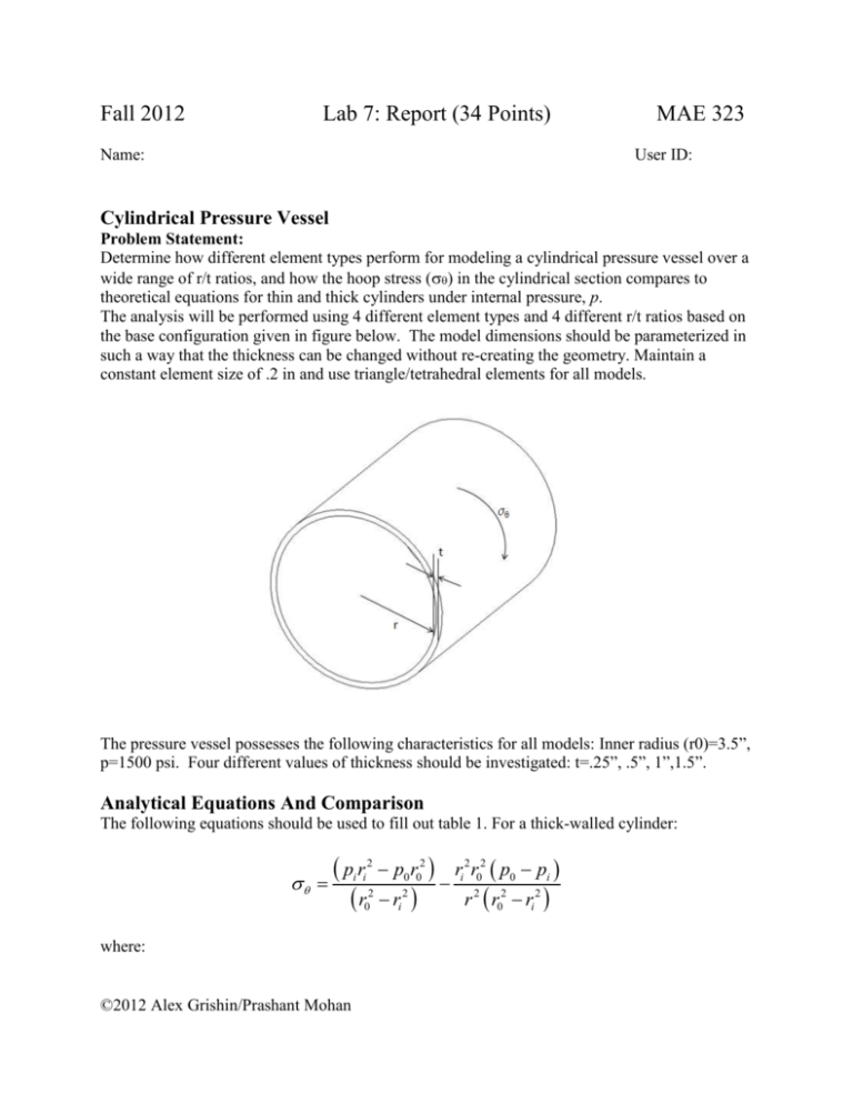
Fall 2012 Lab 7: Report (34 Points) Name: MAE 323 User ID: Cylindrical Pressure Vessel Problem Statement: Determine how different element types perform for modeling a cylindrical pressure vessel over a wide range of r/t ratios, and how the hoop stress () in the cylindrical section compares to theoretical equations for thin and thick cylinders under internal pressure, p. The analysis will be performed using 4 different element types and 4 different r/t ratios based on the base configuration given in figure below. The model dimensions should be parameterized in such a way that the thickness can be changed without re-creating the geometry. Maintain a constant element size of .2 in and use triangle/tetrahedral elements for all models. The pressure vessel possesses the following characteristics for all models: Inner radius (r0)=3.5”, p=1500 psi. Four different values of thickness should be investigated: t=.25”, .5”, 1”,1.5”. Analytical Equations And Comparison The following equations should be used to fill out table 1. For a thick-walled cylinder: pr r 2 i i 2 0 where: ©2012 Alex Grishin/Prashant Mohan p0 r02 ri 2 ri 2 r02 p0 pi r 2 r02 ri 2 hoop stress pi pressure at inner radius p0 pressure at outer radius ri inner radius r0 outer radius r radius of interest* *For r (the radius of interest), use the inner radius (ri) for maximum hoop stress. For a thin-walled cylinder, the following equation should be used: pr t Where t is the thickness of the cylinder. Use the inner radius for r in all cases. Table 1 Hoop Stress for different thickness values (6 Points) Thickness r/t ratio FE shell FE solid FE plane strain FE axisymmetric Theoretical (thin wall) Theoretical (thick wall) 0.25 14.0 0.50 7.0 1.00 3.5 1.50 2.3 Computational Expense Fill out table 2, reporting the total number of DoF’s in each model (remember, this can be obtained by multiplying the number of nodes by the number of number of DoFs per node). Table 2 # DoFs for each model (6 points) FE shell Thickness # DoF 0.25 0.5 1 1.5 FE Solid # DoF FE Plane Strain # DoF FE Axisymmetric # DoF Reference: For thick cylinders: http://www.engineeringtoolbox.com/stress-thick-walled-tube-d_949.html ©2012 Alex Grishin/Prashant Mohan For thin cylinders: http://en.wikipedia.org/wiki/Cylinder_stresses Questions: Comment on the overall limitations and advantages of each element type for this problem (3 points) Axisymmetric elements are planar elements, as are plane strain elements. Comment on the differences or similarities between the axisymmetric and plane strain solutions (Hint: look through the lecture notes. 3 points) Figures Figure 1: Boundary conditions for shell model (show me the model with the smallest thickness (.25”) used in the study. 2 points). . Figure 2: Boundary conditions for solid model (show me the model for the smallest thickness (.25”) used in the study. 2 points). . Figure 3: Boundary conditions for plane strain model (show me the model for the smallest thickness (.25”) used in the study. 2 points). Figure 4: Boundary conditions for axisymmetric model (show me the model for the smallest thickness (.25”) used in the study. 2 points). . Figure 5: Hoop stress for shell model (show me the model with the smallest thickness (.25”) used in the study. 2 points). Figure 6: Hoop stress for solid model (show me the model with the smallest thickness (.25”) used in the study. 2 points). Figure 7: Hoop stress for plane strain model (show me the model with the smallest thickness (.25”) used in the study. 2 points). Figure 8: Hoop stress for axisymmetric model (show me the model with the smallest thickness (.25”) used in the study. 2 points). ©2012 Alex Grishin/Prashant Mohan
