Examination of the structure of NaCl
monocrystals with different orientations
TEP
5.4.1301
Related topics
Characteristic X-radiation, energy levels, crystal structures, reciprocal lattices, Miller indices, atomic form
factor, structure factor, and Bragg scattering
Principle
The spectra of the X-rays that are reflected with various different orientations by NaCl monocrystals are
analysed. The associated interplanar spacings are determined based on the Bragg angles of the characteristic lines.
Equipment
1
1
1
1
1
1
1
1
1
1
XR 4.0 expert unit
X-ray goniometer
X-ray plug-in unit with a Cu X-ray tube
Counter tube, type B
X-ray universal crystal holder for X-ray units
X-ray NaCl monocrystals, set of 3
X-ray diaphragm tube, d = 2 mm
X-ray diaphragm tube, d = 1 mm
measure XRm 4.0 X-ray software
Data cable USB, plug type A/B
09057-99
09057-10
09057-50
09005-00
09058-02
09058-01
09057-02
09057-01
14414-61
14608-00
Additional equipment
PC, Windows® XP or higher
This experiment is included in the upgrade set “XRS 4.0 X-ray structural analysis”.
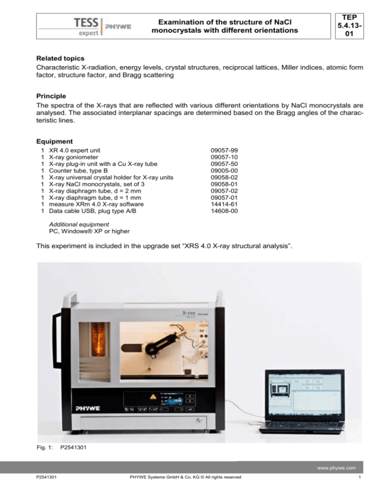
Fig. 1:
P2541301
www.phywe.com
P2541301
PHYWE Systeme GmbH & Co. KG © All rights reserved
1
TEP
5.4.1301
Examination of the structure of NaCl
monocrystals with different orientations
Tasks
1. Determine the intensity of the X-rays that are reflected by the NaCl monocrystals with the orientations [100], [110], and [111] as a function of the Bragg angle.
2. Assign the reflections to the corresponding lattice planes that are given by way of their respective
Miller indices.
3. Determine the lattice constant and calculate the interplanar
spacing.
4. Determine the mass of a cell and the number of atoms in the
cell.
Set-up
Connect the goniometer and the Geiger-Müller counter tube to
their respective sockets in the experiment chamber (see the red
markings in Fig. 2). The goniometer block with the analyser crystal should be located at the end position on the right-hand side.
Fasten the Geiger-Müller counter tube with its holder to the back
stop of the guide rails. Do not forget to install the diaphragm in
front
of
the
counter
tube
(see
Fig.
3a).
Insert a diaphragm tube with a diameter of 2 mm into the beam
outlet of the tube plug-in unit for the collimation of the X-ray beam.
Note
Details concerning the operation of the X-ray unit and goniometer
as well as information on how to handle the monocrystals can be Fig. 2: Connectors in the experiment
chamber
found in the respective operating instructions..
Calibration
Goniometer at
Exact angular positions of Debye-Scherrer reflecthe end position
tions are only to be expected when the goniometer is
correctly adjusted. Should the goniometer be out of
adjustment for any reason whatever, this fault can
be corrected either manually or by means of the autocalibration function.
Counter tube
diaphragm
Automatic calibration:
The anode material of the X-ray tube is automatically identified. The crystal must be manually set under “Menu”, “Goniometer”, “Parameter”.
Mounted
For calibration, select “Menu”, “Goniometer”,
crystal
“Autocalibration”. The device now determines
the optimal positions of the crystal and the goniFig. 3: NaCl crystal in its holder
ometer to each other and then the positions of
the peaks. The display shows the corresponding
calibration curves. The newly configurated zero position of the goniometer system is saved even after switch-off of the X-ray unit.
Manual calibration:
The crystal for analysis must be manually brought to the theoretical Bragg angle ϑ (counter tube correspondingly to 2ϑ). Now search for the intensity maximum of the line by iterative turning of the crystal and counter tube by a few ±1/10° around this angular position. Following this and in coupled
mode, bring the crystal and counter tube to the particular zero position corrected by the error value
and then confirm with “Menu”, “Goniometer” and “Set to zero”.
2
PHYWE Systeme GmbH & Co. KG © All rights reserved
P2541301
TEP
5.4.1301
Examination of the structure of NaCl
monocrystals with different orientations
Procedure
- Connect the X-ray unit via USB cable to the
USB port of your computer.
- Start the “measure” program. A virtual X-ray unit
will be displayed on the screen.
- You can control the X-ray unit by clicking the
various features on and under the virtual X-ray
unit. Alternatively, you can also change the parameters at the real X-ray unit. The program will
automatically adopt the settings.
- Click the experiment chamber to change the parameters for the experiment. Select the parameters as shown in Figure 6.
- If you click the X-ray tube, you can change the
voltage and current of the X-ray tube. Select the
following: anode voltage UA = 35 kV; anode current IA = 1 mA.
- Mount one of the crystals in the universal crystal
holder and attach it to the goniometer (Fig. 3).
- Start the measurement by clicking the red circle
Note
Never expose the Geiger-Müller counter tube to
the primary X-radiation for an extended period of
time.
Overview of the settings of the goniometer
and X-ray unit:
- 2:1 coupling mode
- Gate time 2 s; angle step width 0.1°
- Scanning range 3°-60°
- Anode voltage UA = 35 kV; anode current
IA = 1 mA
Fig. 4: Connection of the computer
For setting the
X-ray tube
For setting the
goniometer
Fig. 5: Part of the user interface of the software
Theory
If X-rays hit a parallel lattice plane family with the
interplanar distance d under the glancing angle ϑ,
the radiation will be reflected in a constructive
manner provided that the so-called Bragg condition (2) is fulfilled (see Figure 7).
2d sin n ; (n = 1, 2, 3,…)
(1)
Fig. 6: Settings of the goniometer, NaCl (100) crystal
www.phywe.com
P2541301
PHYWE Systeme GmbH & Co. KG © All rights reserved
3
TEP
5.4.1301
Examination of the structure of NaCl
monocrystals with different orientations
In the context of crystal structure analyses, n is often
integrated into the distance between the lattice
planes.
2d sin
(1b)
Fig. 8a: NaCl crystal with a drawn-in (100) lattice planes
Fig. 7: Bragg scattering on the lattice planes
The reflections of the nth order are directly assigned to
the diffraction on the various planes.
The Miller indices are a method for naming the various planes in a crystal.
They basically indicate the points of intersection of an
imaginary section through the three-dimensional unit
cell of the crystal.
The symmetrical fundamental unit of a crystal is the
unit cell. In a cubic crystal lattice, like in the case of
NaCl, all of the sides of this cell are of the same
length. The side length of such a cell is referred to as
the lattice constant a.
Fig. 8b: NaCl crystal with a drawn-in (110) lattice plane
As shown in Figures 8a to 8c, NaCl monocrystals
have a face-centred cubic lattice (fcc). In the primitive
cell, an Na+ ion has the coordinates (0,0,0) and a Clion has the coordinates (½,½,½). For a cubic crystal
with a lattice constant a, the lattice planes that are
characterised by the miller indices (h,k,l) have the following interplanar spacing d:
d
a
h k l
2
2
(2)
2
Putting (2) into (1b) results in the following connection:
sin hkl h 2 k 2 l 2
2a
(2b)
Fig. 8c: NaCl crystal with drawn-in (111) and (222) lattice planes. Na+ ions = ●; Cl- ions = O.
The relative intensity of the reflected radiation is determined by the scattering power and position of the
individual atoms in the unit cell of the crystal. It is described by the so-called structure factor F(h,k,l):
4
PHYWE Systeme GmbH & Co. KG © All rights reserved
P2541301
TEP
5.4.1301
Examination of the structure of NaCl
monocrystals with different orientations
F h, k , l f n exp 2ihu n kvn lwn
n
(3)
In this equation (3), fn = the atomic form factor (atomic scattering factor), and un, vn, and wn = the coordinates of the nth atom in the unit cell. The total backscattered beam intensity I is:
I F * F F h, k , l
2
(4)
(4)
With the 000; 0 ½ ½; ½ 0 ½; and ½ ½ 0 of the basis atoms in the unit cell of an fcc crystal, it follows from
(3) that F = 0 when the h,k,l triplet contains even and odd numbers, and F = 4f when all of the indices
are either even or odd. In addition, in face-centred cubic crystal structures and in the case of the 100 and
110 lattice planes, the reflections of the planes with odd values for h, k, and l are eliminated by systematic extinction. Please refer to the corresponding specialised textbooks.
Evaluation
Task 1: Determine the intensity of the X-rays that are reflected by the NaCl monocrystals with the orientations [100], [110], and [111] as a function of the Bragg angle.
Figure 9a to 9c show the spectra of various NaCl crystals.
Compared to the other spectra, the spectrum of the [111] crystal (Fig. 9c) shows a noticeable feature.
While in the case of the other spectra, the intensity of the characteristic lines is always the highest for the
first order (n = 1) reflections. This is the case with n = 2 in Figure 9c.
Fig. 9a: Intensity of the X-ray spectrum of copper as a function of the glancing
angle ϑ: NaCl monocrystals with different orientations as Bragg analysers: [100] crystal orientation
www.phywe.com
P2541301
PHYWE Systeme GmbH & Co. KG © All rights reserved
5
TEP
5.4.1301
Examination of the structure of NaCl
monocrystals with different orientations
Fig. 9b: [110] orientation
Fig. 9c: [111] orientation
In the [111] crystal, the parallel lattice planes are occupied either only by Na+ ions or by Cl- ions. As
these two ions have different scattering factors, the intensities also differ from each other. If fNa and fCl
are the scattering factors, the following results from (3) for lattice planes with solely odd (h,k,l) indices:
F 4 f Na f Cl
I F 2 16 f Na f Cl
2
and
Accordingly, the following is true for the intensity that is reflected by latticed planes with solely even indices:
F 4 f Na f Cl
6
I F 2 16 f Na f Cl
2
and
PHYWE Systeme GmbH & Co. KG © All rights reserved
P2541301
TEP
5.4.1301
Examination of the structure of NaCl
monocrystals with different orientations
Task 2: Assignment of the Miller indices
In Table 1, the glancing angles ϑ that were determined with the aid of Figures 6a to 6c are assigned to their respective Miller indices. Based
on (3), we know that for the 100 and 110 lattice
planes only even or only odd values are possible
for the h, k, l triplet and that there are in fact no
reflections for odd values of h, k, and l at 100 and
110. These considerations resulted in the assignments shown in Table 1.
Task 3: Determine the lattice constant and calculate the interplanar spacing.
If one solves equation (2b) for a, one obtains the
lattice constant a for the various reflections based
on the hkl triplets that were determined in Task 1
as well as based on the glancing angle ϑ and the
wavelength of the characteristic X-radiation of
copper (λKα = 154.4 pm; λKβ = 139.2 pm). Table 2
shows the corresponding values. A comparison of
the average value with the literature value of a =
564 pm shows good correspondence.
Equation (2) can now be used to calculate the interplanar spacing for the first plane since the lattice constant a refers to a unit cell with only two
planes.
With this value and in accordance with equation
(1), the distances between the individual lattice
planes are as follows: d(200) = 282.0 pm, d(220)
= 201.9 pm, and d(111) = 330.2 pm.
Literature values: d(200) = 282.0 pm, d(220) =
199.4 pm, and d(111) = 325.6 pm.
Table 1
ϑ(Kα)/°
ϑ(Kβ)/°
(hkl)
(h2+k2+l2)
15.9
33.2
55.1
14.3
29.7
47.9
200
400
600
4
16
36
22.3
50.2
20.1
43.9
220
440
8
32
13.5
28.1
45.0
-
12.1
25.1
39.7
58.5
111
222
333
444
3
12
27
48
(100) crystal
(110) crystal
(111) crystal
Table 2
ϑ/°
(hkl)
(h2+k2+l2)
a/pm
Kα
15.9
200
4
567
Kβ
33.2
55.1
14.3
400
600
200
16
36
4
564
565
564
29.7
47.9
400
600
16
36
Mean value
562
563
564
22.3
220
8
575
50.2
20.1
440
220
32
8
568
573
43.9
440
32
Mean value
568
571
13.5
111
3
573
28.1
45.0
12.1
222
333
111
12
27
3
586
567
575
25.1
39.7
58.5
222
333
444
12
27
48
Mean value
568
566
566
572
(100) crystal
(110) crystal
Kα
Kβ
(111) crystal
Kα
Kβ
The very good agreement between the value for
the distance between the (100) lattice planes that
was determined experimentally and the literature
value is due to the fact that ionic crystals can be
split very exactly in parallel to this plane. The deviations of the other crystals are due to a slight misorientation.
www.phywe.com
P2541301
PHYWE Systeme GmbH & Co. KG © All rights reserved
7
TEP
5.4.1301
Examination of the structure of NaCl
monocrystals with different orientations
Task 4: Determine the mass of a cell and the number of atoms in the cell.
If one calculates the volume of the unit cell of sodium chloride
a3= 1.79 ×10⁻²⁸m3
the density of sodium chloride of ρ= 2.163 g/cm³ leads to the weight of a unit cell as
m= ρ.V=2.163 g/cm³.1.79 ×10-28m3
3.87.10-25kg =233u
with the atomic mass unit 1 u = 1.661 . 10-27 kg.
Since the number of Na atoms in NaCl equals the
number of Cl atoms, the molar masses M(Na) =
22.990g/mol and M(Cl) = 35.453g/mol lead to a number of 3.99 = 4 atoms each in the Bravais lattice,
which could also be expected for an fcc lattice based
on the following considerations (see also Fig. 10):
Every unit cell includes 4
(green) cations:
Each of the cations at the 8 corners of the unit cell counts as
only 1/8 to the unit cell since only 1/8 of the volume actually lies
within the unit cell.
8 “corner cations” .
1/8 = 1 cation
The cations on the surfaces
count as only 1/2:
6 “surface cations” .
1/2 = 3 cations
Fig. 10: The unit cell of NaCl, blue: Cl atoms; green: Na atoms
Resulting total
number: 4 cations
Every unit cell includes 4 (blue)
anions:
Each of the anions at the 12
edges counts as only ¼ to the
unit cell:
12 “edge anions” .
1/4 = 3 anions
The anion in the centre belongs
completely to the unit cell:
1 “centre anion” .
1/1 = 1 anion
Resulting total
number: 4 anions
8
PHYWE Systeme GmbH & Co. KG © All rights reserved
P2541301


