Ch. 23, sections 4,5, 7, 8, 9 Section 4 c= 3 e 8 m/s (speed of light in a
Ch. 23, sections 4,5, 7, 8, 9
Section 4 c= 3 e 8 m/s (speed of light in a vacuum)
Index of refraction:
ratio of c to speed (v) of any given material. n= c/v (n being index of refraction)
n > or = to 1
ex 23-7, page 696
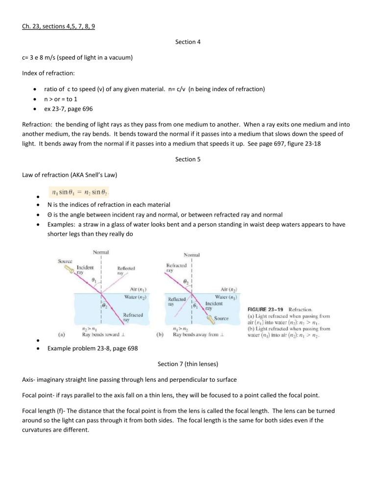
Refraction: the bending of light rays as they pass from one medium to another. When a ray exits one medium and into another medium, the ray bends. It bends toward the normal if it passes into a medium that slows down the speed of light. It bends away from the normal if it passes into a medium that speeds it up. See page 697, figure 23-18
Section 5
Law of refraction (AKA Snell’s Law)
N is the indices of refraction in each material
Θ is the angle between incident ray and normal, or between refracted ray and normal
Examples: a straw in a glass of water looks bent and a person standing in waist deep waters appears to have shorter legs than they really do
Example problem 23-8, page 698
Section 7 (thin lenses)
Axis- imaginary straight line passing through lens and perpendicular to surface
Focal point- if rays parallel to the axis fall on a thin lens, they will be focused to a point called the focal point.
Focal length (f)- The distance that the focal point is from the lens is called the focal length. The lens can be turned around so the light can pass through it from both sides. The focal length is the same for both sides even if the curvatures are different.
Converging lens- any lens that is thicker at the center than at the edges will make rays converge to a point and are called converging lenses.
Diverging lens- Lenses that are thinner in the center than at the edges are called diverging lenses and they make light rays diverge.
Optometrists use the reciprocal of the focal length to specify strength of eyeglasses or contact lenses. This is called the power, P, of a lens. P=1/f
Ray Diagrams for converging lenses: (It is a real image b/c rays actually pass through the image)
Ray Diagrams for diverging lenses: (Because rays do not pass through the image, it is a virtual image)
Step-by-Step Method for Drawing Ray Diagrams
The method of drawing ray diagrams for a double concave lens is described below.
1. Pick a point on the top of the object and draw three incident rays traveling towards the lens.
Using a straight edge, accurately draw one ray so that it travels towards the focal point on the opposite side of the lens; this ray will strike the lens before reaching the focal point; stop the ray at the point of incidence with the lens. Draw the second ray such that it travels exactly parallel to the principal axis. Draw the third ray to the exact center of the lens. Place arrowheads upon the rays to indicate their direction of travel.
2. Once these incident rays strike the lens, refract them according to the three rules of refraction for double concave lenses.
The ray that travels towards the focal point will refract through the lens and travel parallel to the principal axis. Use a straight edge to accurately draw its path. The ray that traveled parallel to the principal axis on the way to the lens will refract and travel in a direction such that its extension passes through the focal point on the object's side of the lens. Align a straight edge with the point of incidence and the focal point, and draw the second refracted ray. The ray that traveled to the exact center of the lens will continue to travel in the same direction. Place arrowheads upon the rays to indicate their direction of travel. The three rays should be diverging upon refraction.
Section 8 & 9
The lens equation:
Magnification of lens:
Practice Problems 23-11, 23-12, and 23-13—pages 708-709

