Supplemental materials-2
advertisement
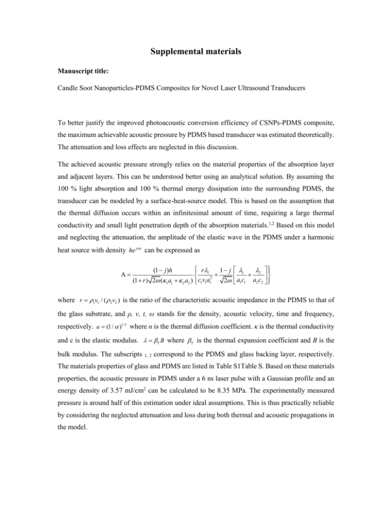
Supplemental materials Manuscript title: Candle Soot Nanoparticles-PDMS Composites for Novel Laser Ultrasound Transducers To better justify the improved photoacoustic conversion efficiency of CSNPs-PDMS composite, the maximum achievable acoustic pressure by PDMS based transducer was estimated theoretically. The attenuation and loss effects are neglected in this discussion. The achieved acoustic pressure strongly relies on the material properties of the absorption layer and adjacent layers. This can be understood better using an analytical solution. By assuming the 100 % light absorption and 100 % thermal energy dissipation into the surrounding PDMS, the transducer can be modeled by a surface-heat-source model. This is based on the assumption that the thermal diffusion occurs within an infinitesimal amount of time, requiring a large thermal conductivity and small light penetration depth of the absorption materials.1,2 Based on this model and neglecting the attenuation, the amplitude of the elastic wave in the PDMS under a harmonic heat source with density he jt can be expressed as A r1 1 j 2 c v a (1 r ) 2 (1a1 2 a2 ) 1 1 1 2 (1 j )h 1 2 a1c1 a2 c2 where r 1v1 / ( 2 v2 ) is the ratio of the characteristic acoustic impedance in the PDMS to that of the glass substrate, and ρ, ν, t, ω stands for the density, acoustic velocity, time and frequency, respectively. a (1 / )1/ 2 where α is the thermal diffusion coefficient. κ is the thermal conductivity and c is the elastic modulus. T B where T is the thermal expansion coefficient and B is the bulk modulus. The subscripts 1, 2 correspond to the PDMS and glass backing layer, respectively. The materials properties of glass and PDMS are listed in Table S1Table S. Based on these materials properties, the acoustic pressure in PDMS under a 6 ns laser pulse with a Gaussian profile and an energy density of 3.57 mJ/cm2 can be calculated to be 8.35 MPa. The experimentally measured pressure is around half of this estimation under ideal assumptions. This is thus practically reliable by considering the neglected attenuation and loss during both thermal and acoustic propagations in the model. Table S1. The material properties of transducer layers.3 κ α × 10-7 βT × 10-6 ν ρ B (Wm-1K-1) (m2s-1) (K-1) (ms-1) (kgm-3) (GPa) Glass 1.38 8.48 0.55 5900 2200 50 PDMS 0.15 1.06 920 1076 970 7.7 The explanation of the improved photoacoustic conversion efficiency in CSNPs-PDMS composite is described below. Based on the one dimension model the most effective elastic-wave generation occurs when materials in or adjacent to the heated region have large values of βT(D)1/2 where D is the thermal diffusion distance which equals D 2 / .1 It should be noted that these parameters 1/ 2 are the effective values of the composite thus determined by not only the materials composition but also the spatial structure configuration. At 10 MHz, the thermal diffusion distance in PDMS is 60 nm while as high as 11 µm in CSNPs. The hierarchical and arborized structure of the CSNPs allow the thermal energy to transfer to a large distance within a short amount of time and dissipate into the surrounding PDMS more uniformly and faster. In contrast, the aggregated CBs are isolated by the surrounding PDMS matrix which blocks the efficient thermal transfer. Therefore, higher effective thermal diffusion distance can be expected in CSNPs-PDMS composite compared that of the CB-PDMS composite, resulting in a higher photoacoustic conversion efficiency. The observed narrower frequency bandwidth of CB-PDMS composite is believed to arise from the non-uniform mixing and dispersion of CB particles in the PDMS matrix. The generated pulse shape is most dependent on the optical attenuation coefficient β and the acoustic attenuation property. As β-1 increases, the pulse width becomes narrow and sharper profile is expected until saturation occurs. The pulse width is around 5β-1 before saturation, or five penetration depths.1 The penetration depth of CB alone resides between 10 ~ 15 nm where pulse width already saturates.4 However, with low CB concentration in the PDMS polymer, the penetration depth could reach hundreds of µm. 5,6 A 100 µm penetration depth yield a 300 ns pulse width thus a narrow frequency bandwidth. This can be induced by the aggregation of CB, leaving numerous porous PDMS areas where light could travel deep. The acoustic attenuation is unlikely to be the reason for the narrower bandwidth of CBPDMS as the total thickness of each composite is similar thus the attenuation levels are expected to be equivalent. 1 2 3 4 5 6 G. C. Wetsel Jr, IEEE transactions on ultrasonics, ferroelectrics, and frequency control (5), 450 (1986). R. M. White, J Appl Phys 34 (12), 3559 (1963). L. H. Tong, C. W. Lim, and Y. C. Li, Journal of Applied Mechanics 81 (8), 081014 (2014). J.-B. Donnet, Carbon black: science and technology. (CRC Press, 1993). F. Bachmann, P. Loosen, and R. Poprawe, High power diode lasers: technology and applications. (Springer, 2007). Y. Tian, N. Wu, K. Sun, X. Zou, and X. Wang, Journal of Computational Acoustics 21 (02) (2013).
