Figure 1: Zonal mean top of the atmosphere short wave (TOA
advertisement
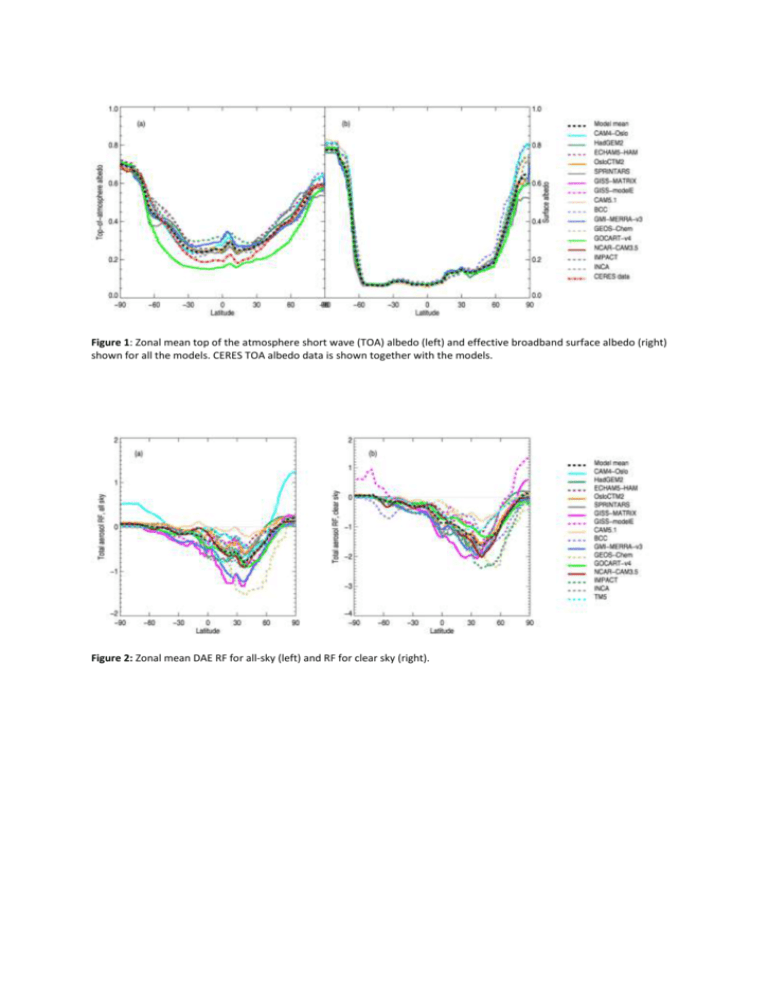
Figure 1: Zonal mean top of the atmosphere short wave (TOA) albedo (left) and effective broadband surface albedo (right) shown for all the models. CERES TOA albedo data is shown together with the models. Figure 2: Zonal mean DAE RF for all-sky (left) and RF for clear sky (right). Figure 3: Anthropogenic AOD (upper left), anthropogenic AAOD (upper right), anthropogenic single scattering albedo (lower left), and change in single scattering albedo from pre-industrial to present conditions (lower right). All values are taken at 550nm. Between 80S and 30S the anthropogenic AOD is extremely small for some of the models and anthropogenic single scattering albedo may reach unrealistic values and in such cases values have been removed from the figure. Figure 4: Radiative forcing from the six components, overlain with the (unmodified) model total forcing (yellow bars). Figure 5: Model total RFs. Black bars show the bare modelled forcing, the colored bars show the forcing modified for untreated components (see text for details). The yellow bar shows the AeroCom mean of the total RF of DAE. Solid lines inside the boxes show the model mean, dashed lines show the median. The boxes indicate one standard deviation, while the whiskers indicate the max and min of the distribution. The yellow shaded bar shows the AeroCom mean when aerosol component adjustment is made for missing aerosol components. Figure 6: Correlation between anthropogenic absorption AOD and atmospheric absorption. Numbers show ratio AtmAbs/AAOD, the lines indicate the mean and one standard deviation of this ratio. R2 = 0.73 Figure 7: Component and total RF. Total RF has been modified for missing components in individual models. Solid lines inside the boxes show the model mean, dashed lines show the median. The boxes indicate one standard deviation, while the whiskers indicate the max and min of the distribution. Figure 8: Zonal mean SO4 RF, burden, AOD at 550nm, normalized RF with respect to AOD (NRF(A)) Figure 9: Zonal mean BC RF, burden, AOD at 550nm, NRF(A). For GEOS-CHEM the RF of BC has been derived as the total DAE minus the contribution from the non-BC aerosol components. This treatment has been applied due to the mixing assumption in this model makes removal of all anthropogenic BC unrealistic in relations to the total DAE. Figure 10: Zonal mean OAFF RF, burden, AOD at 550nm, NRF(A) Figure 11: Zonal mean SOA RF, burden, AOD at 550nm, NRF(A) Figure 12: Zonal mean NO3 RF, burden, AOD at 550nm, NRF(A) Figure 13: Model mean RF (left) and standard deviation (right). Figure 14: Aerosol forcing partial sensitivities for the AeroCom models. The partial senistivities are calculated as P x,n = xn / <x> * <RF>, where n is model, x is either burden, MEC, NRF (with respect to AOD) or RF, <> denote mean values. Black dotted line is the mean of the AeroCom models. (Some of the results from the GISS-models are removed due to unresolved issues). Figure 15: Model mean RF per component (internal bars), modified from the study timeperiod of 1850-2000 to 1750-2010, based on numbers from Skeie et al. 2011. Details to be given in text. Figure 16: Correlations between burdens (left column), RF (middle) and normalized forcing (right), for SO4 vs BCFF (top row) and OCFF vs BCFF (bottom row). Corr. Coeffs (R2): a) 0.25, b) -0.73, c) 0.13, d) 0.13, e) -0.47, f) 0.03 Figure 17: Normalized PDFs of each aerosol component RF (dashed lines) based on the model spread shown above. The red line shows the mean of the modeled total aerosol RF, while the black line shows the spread when correcting for missing components as explained in the text. Supplementary figure 1: Zonal mean BB RF, burden, AOD at 550nm, NRF(A)

