Abstract
advertisement
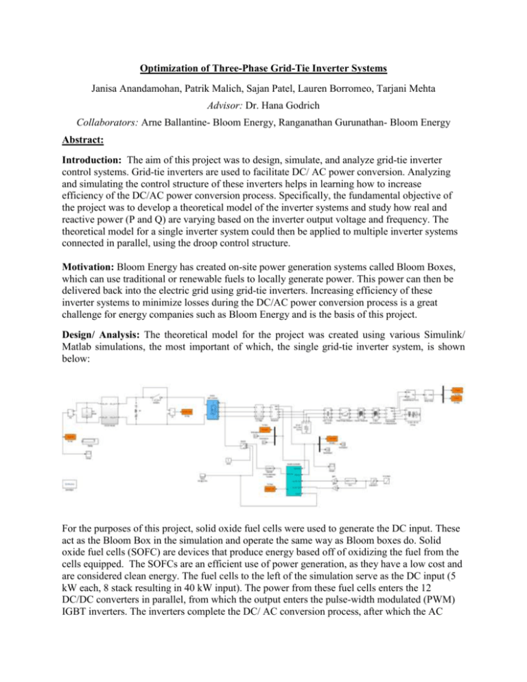
Optimization of Three-Phase Grid-Tie Inverter Systems Janisa Anandamohan, Patrik Malich, Sajan Patel, Lauren Borromeo, Tarjani Mehta Advisor: Dr. Hana Godrich Collaborators: Arne Ballantine- Bloom Energy, Ranganathan Gurunathan- Bloom Energy Abstract: Introduction: The aim of this project was to design, simulate, and analyze grid-tie inverter control systems. Grid-tie inverters are used to facilitate DC/ AC power conversion. Analyzing and simulating the control structure of these inverters helps in learning how to increase efficiency of the DC/AC power conversion process. Specifically, the fundamental objective of the project was to develop a theoretical model of the inverter systems and study how real and reactive power (P and Q) are varying based on the inverter output voltage and frequency. The theoretical model for a single inverter system could then be applied to multiple inverter systems connected in parallel, using the droop control structure. Motivation: Bloom Energy has created on-site power generation systems called Bloom Boxes, which can use traditional or renewable fuels to locally generate power. This power can then be delivered back into the electric grid using grid-tie inverters. Increasing efficiency of these inverter systems to minimize losses during the DC/AC power conversion process is a great challenge for energy companies such as Bloom Energy and is the basis of this project. Design/ Analysis: The theoretical model for the project was created using various Simulink/ Matlab simulations, the most important of which, the single grid-tie inverter system, is shown below: For the purposes of this project, solid oxide fuel cells were used to generate the DC input. These act as the Bloom Box in the simulation and operate the same way as Bloom boxes do. Solid oxide fuel cells (SOFC) are devices that produce energy based off of oxidizing the fuel from the cells equipped. The SOFCs are an efficient use of power generation, as they have a low cost and are considered clean energy. The fuel cells to the left of the simulation serve as the DC input (5 kW each, 8 stack resulting in 40 kW input). The power from these fuel cells enters the 12 DC/DC converters in parallel, from which the output enters the pulse-width modulated (PWM) IGBT inverters. The inverters complete the DC/ AC conversion process, after which the AC output is fed into the utilities and measured at the 12.5 kW load (to the right). Real and reactive power (P and Q respectively) are measured and compared to the inputted DC value, measured at the load. Loads are changed to evaluate how load impacts power outputs in the system and then the controller is designed to minimize power losses caused by changes in load. In the model, the control system is an open loop feedback system, where the controller is a three-arm bridge, which has six pulses with a 4860 Hertz frequency. Conclusion: The project is successful in clearly defining a grid-tie inverter system model and relationships for the parameters specified by Bloom Energy in it. In the future, this theoretical control system model can be implemented physically, using hardware provided by Bloom Energy. Also, the relationships discovered in this theoretical modeling process can be used to create a model for multiple grid-tie inverter systems with inverters in parallel on a single output, using the droop control structure. The goal of this would be to make the DC/AC conversion more cost effective and energy efficient. These factors are important for the long term development of smart-grid control structures and on-site power generation units as a whole.
