Krupka_suplementary2a
advertisement
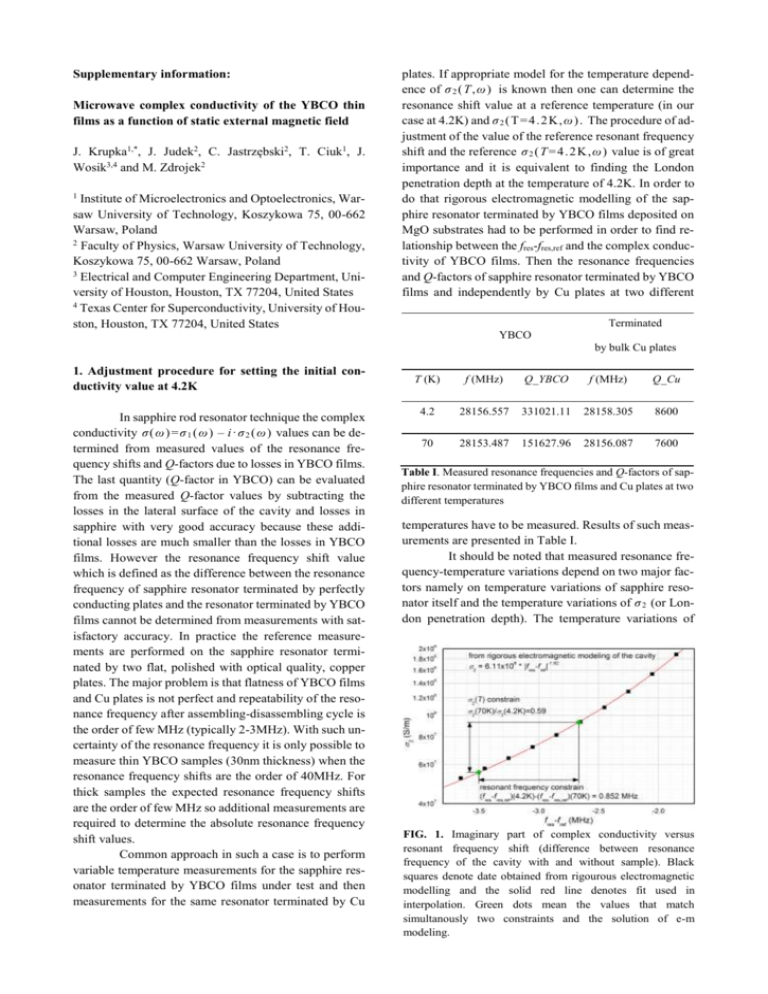
Supplementary information: Microwave complex conductivity of the YBCO thin films as a function of static external magnetic field J. Krupka1,*, J. Judek2, C. Jastrzębski2, T. Ciuk1, J. Wosik3,4 and M. Zdrojek2 1 Institute of Microelectronics and Optoelectronics, Warsaw University of Technology, Koszykowa 75, 00-662 Warsaw, Poland 2 Faculty of Physics, Warsaw University of Technology, Koszykowa 75, 00-662 Warsaw, Poland 3 Electrical and Computer Engineering Department, University of Houston, Houston, TX 77204, United States 4 Texas Center for Superconductivity, University of Houston, Houston, TX 77204, United States plates. If appropriate model for the temperature dependence of σ 2 ( T,ω ) is known then one can determine the resonance shift value at a reference temperature (in our case at 4.2K) and σ 2 (T =4 .2 K, ω ). The procedure of adjustment of the value of the reference resonant frequency shift and the reference σ 2 ( T = 4 .2 K, ω ) value is of great importance and it is equivalent to finding the London penetration depth at the temperature of 4.2K. In order to do that rigorous electromagnetic modelling of the sapphire resonator terminated by YBCO films deposited on MgO substrates had to be performed in order to find relationship between the fres-fres,ref and the complex conductivity of YBCO films. Then the resonance frequencies and Q-factors of sapphire resonator terminated by YBCO films and independently by Cu plates at two different Terminated YBCO by bulk Cu plates 1. Adjustment procedure for setting the initial conductivity value at 4.2K In sapphire rod resonator technique the complex conductivity σ( ω ) =σ 1 ( ω ) – i· σ 2 ( ω ) values can be determined from measured values of the resonance frequency shifts and Q-factors due to losses in YBCO films. The last quantity (Q-factor in YBCO) can be evaluated from the measured Q-factor values by subtracting the losses in the lateral surface of the cavity and losses in sapphire with very good accuracy because these additional losses are much smaller than the losses in YBCO films. However the resonance frequency shift value which is defined as the difference between the resonance frequency of sapphire resonator terminated by perfectly conducting plates and the resonator terminated by YBCO films cannot be determined from measurements with satisfactory accuracy. In practice the reference measurements are performed on the sapphire resonator terminated by two flat, polished with optical quality, copper plates. The major problem is that flatness of YBCO films and Cu plates is not perfect and repeatability of the resonance frequency after assembling-disassembling cycle is the order of few MHz (typically 2-3MHz). With such uncertainty of the resonance frequency it is only possible to measure thin YBCO samples (30nm thickness) when the resonance frequency shifts are the order of 40MHz. For thick samples the expected resonance frequency shifts are the order of few MHz so additional measurements are required to determine the absolute resonance frequency shift values. Common approach in such a case is to perform variable temperature measurements for the sapphire resonator terminated by YBCO films under test and then measurements for the same resonator terminated by Cu T (K) f (MHz) Q_YBCO f (MHz) Q_Cu 4.2 28156.557 331021.11 28158.305 8600 70 28153.487 151627.96 28156.087 7600 Table I. Measured resonance frequencies and Q-factors of sapphire resonator terminated by YBCO films and Cu plates at two different temperatures temperatures have to be measured. Results of such measurements are presented in Table I. It should be noted that measured resonance frequency-temperature variations depend on two major factors namely on temperature variations of sapphire resonator itself and the temperature variations of σ 2 (or London penetration depth). The temperature variations of FIG. 1. Imaginary part of complex conductivity versus resonant frequency shift (difference between resonance frequency of the cavity with and without sample). Black squares denote date obtained from rigourous electromagnetic modelling and the solid red line denotes fit used in interpolation. Green dots mean the values that match simultanously two constraints and the solution of e-m modeling. sapphire resonator can be found as the difference between the resonance frequencies at 70K and 4.2K measured with copper plates while the total variations as the difference between the resonance frequencies at 70K and 4.2K measured with YBCO films. It should be noted that the resonance frequency variations due to the temperature change of the skin depth for copper plates is small and can be neglected (Q-factors with Cu plates are close each other at 4.2K and 70K as it is seen in the last column of Table I). Therefore the resonance frequency shift due to the temperature change of σ 2 for YBCO from the measurement results in Table I can be found as: (𝑓70 − 𝑓4.2 )YBCO = (𝑓70 − 𝑓4.2 )YBCO+sapphire − (𝑓70 − 𝑓4.2 )Cu(sapphire) (1) In our previous work1Error! Bookmark not defined. the temperature studies of the complex conductivity of various YBCO films from the same manufacturer (THEVA) as those that are used in our current work have been performed. We revealed that temperature dependence of our YBCO films well suits to the following model: σ2(T)= σ2(0)·[1-(T/Tc)4], despite the fact that the model rather applies to s-wave superconductors, while YBCO has been known as a d-wave superconductor. From this model one can calculate the ratio of conductivities at 4.2K and 70K as: 𝜎2 (𝑇=70K) 𝜎2 (𝑇=70K) = 0.59 (2) Having known theoretical dependence of the resonance frequency shift on the conductivity σ2 as well as the two constrains: measured resonance frequency shift (1) and conductivity ratio (2) one can uniquely determine the absolute value of σ2 at 4.2K as it is shown in FIG. 1. 2. Discussion on differences between complex conductivity and surface impedance approaches In the fundamental electrodynamics (Maxwell equations in the complex form that are valid for time harmonic electromagnetic fields) the following basic relations are introduced: a) complex permittivity that includes conductivity term 𝜀 = 𝜀0 𝜀r = 𝜀0 (𝜀r′ − i𝜀r" − i 𝜎 𝜔𝜀0 ) (3a) b) complex wave impedance 𝑍𝑤 = √ 𝜇 𝜀 (3b) For nonmagnetic materials (such as dielectric or YBCO) both the complex permittivity and the complex wave impedance can be alternatively used to characterize bulk material. At microwave frequencies electromagnetic fields in conductors and superconductors are atten- uated and exponentially decay in the direction perpendicular to the surface with can be described by one parameter namely the attenuation constant 𝛼 which is defined as the real part of the propagation constant 𝛾. 𝛾 = 𝛼 + i𝛽 = √−𝜔 2 𝜀𝜇 (4) It should be noted that for superconductors the conductivity 𝜎 is the complex quantity 𝜎 = 𝜎1 − i𝜎2 with the imaginary part 𝜎2 which is larger than the real part 𝜎1 . Substituting the complex conductivity into equations (3a) and (4) one can notice that electromagnetic fields are attenuated in superconductors mainly (but not entirely) due to the presence of the imaginary part of conductivity. In metals or in superconductors in the normal state (at temperatures above the critical temperature) attenuation is entirely due to the presence of the real part of conductivity. The length over which the electromagnetic field decays by a factor of e is called the penetration depth λ for superconductors and skin depth for normal conductors. In both cases It can be evaluated from the same formulae as λ = 1/α , or as 𝛿 = 1/α . If the thickness of a sample made from superconducting or conducting material is larger than the penetration depth or the skin depth then the electromagnetic fields in the internal part of the sample are negligibly small and the sample can be considered as being made of thin material having thickness equal to the penetration depth or the skin depth and its properties can be alternatively described either by the complex wave impedance (which is often called the surface impedance) or by the complex permittivity (complex conductivity). The wave (surface) impedance approach is commonly used in the electrodynamics of superconductors. The problem becomes more complicated when the thickness of the sample becomes smaller than the penetration depth or the skin depth. In such cases the complex wave impedance – which is defined on the surface of the sample depends not only on the material properties of the sample (i.e. its complex permittivity or complex conductivity) but also on the properties of layers that lay behind the conducting or superconducting film. Impedance transformation approach which is valid for layer structures and for TEM electromagnetic waves in free space still can be successfully used for analysis of resonators containing such structures (with some limitations that were discussed in [1]) but one cannot interpret the wave impedance of the layered structure as the material property of the conducting (superconducting) film. For this reason the complex permittivity (complex conductivity) approach is more general than the complex impedance approach and what is more important it allows to be directly implemented in the modern electromagnetic simulators. 1 J. Krupka, J. Wosik, C. Jastrzębski, M. Zdrojek, T.Ciuk, and J. Mazierska, IEEE Trans. Appl. Supercond 23, 1501011, (2013). * Author to whom correspondence should be addressed. Electronic mail: krupka@imio.pw.edu.pl
