Velocity and Acceleration Calculations
advertisement
Quadrature Encoder – Velocity and Acceleration Calculations
There can be multiple ways to determine the angular velocity and acceleration of a Quadrature Encoder. In
this tutorial we will develop an example that will count the number of Quadrature Encoder pulses in a fixed
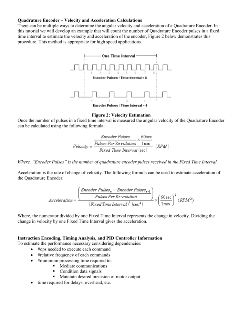
time interval to estimate the velocity and acceleration of the encoder, Figure 2 below demonstrates this
procedure. This method is appropriate for high speed applications.
Figure 2: Velocity Estimation
Once the number of pulses in a fixed time interval is measured the angular velocity of the Quadrature Encoder
can be calculated using the following formula:
Where, “Encoder Pulses” is the number of quadrature encoder pulses received in the Fixed Time Interval.
Acceleration is the rate of change of velocity. The following formula can be used to estimate acceleration of
the Quadrature Encoder:
Where, the numerator divided by one Fixed Time Interval represents the change in velocity. Dividing the
change in velocity by one Fixed Time Interval gives the acceleration.
Instruction Encoding, Timing Analysis, and PID Controller Information
To estimate the performance necessary considering dependencies:
#ops needed to execute each command
#relative frequency of each commands
#minimum processing time required to:
Mediate communications
Condition data signals
Maintain desired precision of motor output
time required for delays, overhead, etc.
Elaborating on these to include system parameters yields:
bits needed for motor control velocities: #signals = (Vmax – Vmin) / precision
For example, if 4.5 m/s is desired with a .1 m/s precision then (4.5 – 0) / .1 = 45 (or, with a bit for
direction, 90) Thus approximately 7 bits is needed.
For the sensors, the equation is similar: #bits is function of the range and precision of the sensor.
The data needed for the encoding is: target + instr. code + params …
Lastly, if the cycles needed for the fetching, decoding, execution are Tx, Dx, and Ex respectively
then: Processing lag = Tx + Dx + Ex / clk. freq.
Instruction Encoding
Dependent on precision of motor -> #bits needed for params
#bits for codeword must cover all necessary commands (~15-20) and should leave room for growth
BW/throughput optimization considerations effect sizing
Must include address of the motor and other components (e.g. sensors)
Consider providing capability for broadcasting to all and to groups
Perhaps include priority to facilitate interrupts and IRQ masking
PID Controller
4 variables:
1. Proportional gain: Kp * Ec
2. Intergral gain: Ki * Ec + Sum{all previous integral terms}
3. Derivate gain: Kd * (En – Ec)
4. Error term (Ec): feedback (motor speed) – set point (set speed)
*number of encoder cnts per unit time
Fig C1.i.a – PID Control
The PID controller is a widely used standard and is effective at accounting for the present (proportional), past
(integral), and future (derivative) deviations from the desired output. Its transfer function is as follows:
There is a major concern when using a PID controller: the parameters must be precisely tuned so that the
system does not continually oscillate around the desired value. Figure C1.i.b shows the results of a simple
simulation where a PID controller is used to maintain a velocity. The three plots correspond to differing
parameter values.
Fig. C1.i.b
The third plot (shown in green) is an example of optimal parameter tuning. There are a variety of ways to tune
these parameters ranging from simple trial and error with varying values to algorithmic approaches such as
Ziegler-Nichols method.
