pre-installation
advertisement
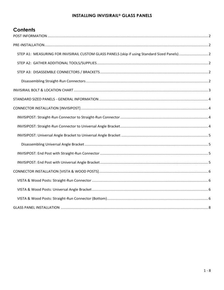
INSTALLING INVISIRAIL® GLASS PANELS Contents POST INFORMATION ............................................................................................................................................................... 2 PRE-INSTALLATION.................................................................................................................................................................. 2 STEP A1: MEASURING FOR INVISIRAIL CUSTOM GLASS PANELS (skip if using Standard Sized Panels) ............................. 2 STEP A2: GATHER ADDITIONAL TOOLS/SUPPLIES .............................................................................................................. 2 STEP A3: DISASSEMBLE CONNECTORS / BRACKETS ........................................................................................................... 2 Disassembling Straight-Run Connectors ......................................................................................................................... 2 INVISIRAIL BOLT & LOCATION CHART ..................................................................................................................................... 3 STANDARD SIZED PANELS - GENERAL INFORMATION ............................................................................................................ 4 CONNECTOR INSTALLATION [INVISIPOST] .............................................................................................................................. 4 INVISIPOST: Straight-Run Connector to Straight-Run Connector ....................................................................................... 4 INVISIPOST: Straight-Run Connector to Universal Angle Bracket ....................................................................................... 4 INVISIPOST: Universal Angle Bracket to Universal Angle Bracket ...................................................................................... 5 Disassembling Universal Angle Bracket .......................................................................................................................... 5 INVISIPOST: End Post with Straight-Run Connector ........................................................................................................... 5 INVISIPOST: End Post with Universal Angle Bracket ........................................................................................................... 5 CONNECTOR INSTALLATION [VISTA & WOOD POSTS] ............................................................................................................ 6 VISTA & Wood Posts: Straight-Run Connector ................................................................................................................... 6 VISTA & Wood Posts: Universal Angle Bracket ................................................................................................................... 6 VISTA & Wood Posts: Straight-Run Connector (Bottom) .................................................................................................... 6 GLASS PANEL INSTALLATION .................................................................................................................................................. 8 1-8 INSTALLING INVISIRAIL® GLASS PANELS POST INFORMATION Posts are always installed first and must be as plumb as possible. PRE-INSTALLATION STEP A1: MEASURING FOR INVISIRAIL CUSTOM GLASS PANELS (skip if using Standard Sized Panels) Distances must be accurate to within +/- 1/16 inches. Measure the opening between straight run posts at the deck surface as this distance is less affected if posts are slightly out of plumb. When ordering glass confirm how many corner posts there will be on the deck. When using Invisiposts on an angle, always measure inside to inside posts, at the hole location on the post. For a 90 degree corner, measure inside face to hole centre on the 90 degree post. For VISTA and wood posts, measure for angle panels at the mid face location of each post. For angle sections, be sure to indicate how many angle brackets are required and the approximate angle at each post. Engineering sheets specify, and glass is marked, for special tempering and heat soaking required for INVISIRAIL. Only glass supplied by Liv Building Products can be used for the INVISIRAIL Glass Railing System. STEP A2: GATHER ADDITIONAL TOOLS/SUPPLIES For All Installations • 2 people are necessary to handle and install glass • Tape measure • Bolt(s) as specified on the INVISIRAIL BOLT & PIN LOCATION CHART When Using Double Universal Angle Connector • Cobalt 5/16” drill bit • Drill with assorted bits • Door shims for fine height adjustments • 2 short pieces 2” x 4”or 4” x 4” to support glass STEP A3: DISASSEMBLE CONNECTORS / BRACKETS Disassembling Straight-Run Connectors Keep all pins and bushings for use later. Consult Invisirail Bolt & Pin Location Chart and other sections of these instructions for when they are required. 2-8 INSTALLING INVISIRAIL® GLASS PANELS INVISIRAIL BOLT & LOCATION CHART Every panel of glass must have AT LEAST one pin on each side (one left and one right) Post Type Application INVISIPOST Top clamp inline Top clamp with angle bracket Top clamp end post Bottom clamp inline Bottom clamp end post VISTA Post Top clamp inline Top clamp end Bottom clamp inline Bottom clamp end Opt for top and bottom Bolt To Use Through Bolt Required Pin Required Distance Off Deck Surface (Y/N/Optional) (Y/N/Optional) (Inches) IB150 IB100 IB100 IB150 IB100 Y Y Y Y Y OPT Y Y Y N 40 40 40 6.5 6.5 VB350 VB300 VB350 VB300 ST125* N N Y Y N N N Y Y Y for both 40 40 6.5 6.5 *Self tapping screws can only be used when pins are used at all connector locations! 4 X 4 Wood Top clamp end Top clamp inline Bottom clamp end Bottom clamp inline WS200 WS200 B425 B475 N N Y Y N N Y Y 40 40 6.5 6.5 6 x 6 Wood WS200 WS200 B625 B675 N N Y Y N N Y Y 40 40 6.5 6.5 Top clamp end Top clamp inline Bottom clamp end Bottom clamp inline Bolt legend WS IB, VB and B (5/16" Capscrew Bolt) ST Followed by length of bolt Wood Screw: # 14 X 2 inch IB = INVISIPOST BOLT, VB = VISTA POST BOLT, B = WOOD POST BOLT Self Tapping Screw: # 14 X 1.50 inch 150 = 1.50 inch e.g. IB150 475 = 4.75 inch For non-standard applications (such as post sleeves of various materials) use a threaded rod with end cap to make custom length bolts. 3-8 INSTALLING INVISIRAIL® GLASS PANELS STANDARD SIZED PANELS - GENERAL INFORMATION Standard glass comes with top hole details AND bottom notches. At least two pins must be installed (one on each side). See supplied chart to determine where pins are to be used and where bolts must pass right through post to hold clamps. To summarize, bottom notches can be used with pins for all VISTA post applications and for 4 X 4 and 6 X 6 wood posts. In this application, the top hole will be covered by the clamp when the clamp is installed. When panels meet in a corner, and a through bolt on each panel will cause interference, the bottom notch pin can be substituted by a top hole pin. Top holes and pins are to be used for all Invisipost end posts, and also when an angles bracket is used. For angle brackets, top holes and pins must be used on both panels adjacent to the angle brackets. For Invisipost NON end panels only, bottom notches and pins can be utilized instead of top holes, if it makes the installation easier. Every panel of glass must have at least one pin on each side of the panel: one on the left and one on the right! CONNECTOR INSTALLATION [INVISIPOST] INVISIPOST: Straight-Run Connector to Straight-Run Connector Disassemble the connectors (see STEP A3 above) Top bracket to be installed 40 inches O/C above deck surface for 42 inch rail height (34 inches for 36 inch rail height) Do not over tighten the lags, causing stripping Only snug up bracket against post so bracket can be still turned by hand force INVISIPOST: Straight-Run Connector to Universal Angle Bracket Disassemble the connectors and brackets (see STEP A3 above) Top bracket to be installed 40 inches O/C above deck surface for 42 inch rail height (34 inches for 36 inch rail height) Do not over tighten the lags, causing stripping Only snug up bracket against post so bracket can be still turned by hand force Using an IB100 (5/16” X 1”), secure brackets to each other by driving the bolt through the straight clamp and into the thread in the angle bracket. 4-8 INSTALLING INVISIRAIL® GLASS PANELS INVISIPOST: Universal Angle Bracket to Universal Angle Bracket Disassemble the brackets (see below) Top bracket to be installed 40 inches O/C above deck surface for 42 inch rail height (34 inches for 36 inch rail height) Do not over tighten the lags, causing stripping Only snug up bracket against post so bracket can be still turned by hand force Disassembling Universal Angle Bracket Disassemble the angle bracket by taking out the locking pin and hinge screw from the hinge. Keep the nylon pin and bushing. Drill out the thread of the mounting hole in the hinge using a cobalt 5/16” diameter bit. *Drill out one bracket only* Insert a short bolt (5/16” X 1”) through the hole drilled out in STEP A3. Insert it through the post, screwing into other angle bracket thread. Complete installation by re-attaching the bracket to the hinge on the angle bracket using set screw and hinge screw. INVISIPOST: End Post with Straight-Run Connector This end run post always needs a pin into the glass. INVISIPOST: End Post with Universal Angle Bracket Screw IB100 (5/16” X 1”) through angle bracket until tight. Fasten hinge to post by tightening bolt with an acorn nut on other side of post. Once the hinge is fastened to post, re-assemble angle bracket. 5-8 INSTALLING INVISIRAIL® GLASS PANELS CONNECTOR INSTALLATION [VISTA & WOOD POSTS] If using VISTA posts, 4” x 4” wood posts, or 6” x 6” wood posts, refer to the INVISIRAIL BOLT & PIN LOCATION CHART. VISTA & Wood Posts: Straight-Run Connector Disassemble the connectors (see STEP A3 above) For top brackets use #14 x 2.5 stainless lag screws (if material is very hard [e.g. Kayu hardwood] pre-drill a pilot) Top bracket to be installed 40 inches O/C above deck surface for 42 inch rail height (34 inches for 36 inch rail height) Do not over tighten the lags, causing stripping Only snug up bracket against post so bracket can be still turned by hand force Drilling Straight-Run Connector into post Top Straight-Run Connector attached to post VISTA & Wood Posts: Universal Angle Bracket Disassemble the brackets (see STEP A3 above) For top brackets use #14 x 2.5 stainless lag screws (if material is very hard [i.e. Kayu] pre-drill a pilot) Top bracket to be installed 40 inches O/C above deck surface for 42 inch rail height (34 inches for 36 inch rail height) Do not over tighten the lags, causing stripping Only snug up bracket against post so bracket can be still turned by hand force Bolts can pass through posts directly into the thread on the angle bracket. VISTA & Wood Posts: Straight-Run Connector (Bottom) Disassemble 2 sets of rail brackets (see STEP A3 above), keeping the pin and nylon bushing aside Drill a 3/8 inch diameter hole through the post, 6.5 o/c inches above the deck surface. Make this hole parallel to the deck (for better accuracy, drill halfway through each side, then drill through hole in one pass) 6-8 INSTALLING INVISIRAIL® GLASS PANELS Drill hole through post to prep for bottom StraightRun Connector install Use a bolt and nut and insert bolt through connector half, push through hole in post, and put the other bracket onto the bolt Put the nut onto the bolt, and spin nut until snug. Use a ¼” drive to snug up the bolt and brackets Setting up bottom connector with bolt, nut, and brackets Connector setup before install When using connectors on a corner, there will only be a bracket on one side. The other side (without the bracket) will have a washer and acorn nut, or support plate, depending on application and engineering sheets. If bolts interfere at corners, use a pin in the top hole instead of a through bolt (on one panel only). The connectors are now ready to install glass, and back half of brackets Finished bottom brackets (both sides) Acorn nut to replace bracket for corner posts 7-8 INSTALLING INVISIRAIL® GLASS PANELS GLASS PANEL INSTALLATION • Use 2 short pieces of 2x4's or 4x4’s, sitting on the deck on edge and in between posts, to support the glass sheets while installing. Door shims help with fine height adjustments. The pins need to be aligned with the holes/notches in the glass. • • • • Locate correct glass panel for section to be installed. Carefully pick up glass sheets and set into position with notches in glass at the bottom. Fasten the top brackets first to hold the panel in position (use pins if required). Take the other half of the brackets, slide onto installed halves, and tighten screws without stripping. • When complete, all bracket plates should be parallel to each other and the screws should be completely tightened. o If the bracket does not slide easily onto installed sections, confirm that the bracket has not been over tightened (this would cause misalignment of the two halves). o The back half of the connector must be completely flush with the front half to ensure the pin is in the holes in both halves of the connector. o Once the pin is perfectly aligned, completely tighten the screws. 8-8
