Diffraction and Interference musgrove - Helios
advertisement
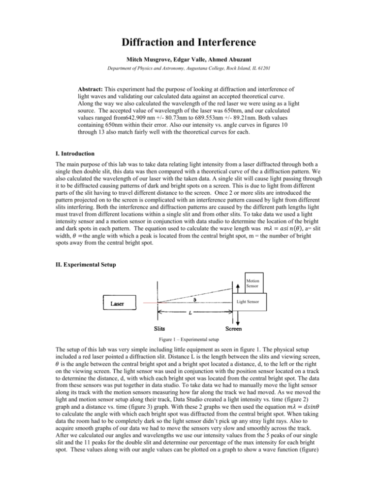
Diffraction and Interference Mitch Musgrove, Edgar Valle, Ahmed Abuzant Department of Physics and Astronomy, Augustana College, Rock Island, IL 61201 Abstract: This experiment had the purpose of looking at diffraction and interference of light waves and validating our calculated data against an accepted theoretical curve. Along the way we also calculated the wavelength of the red laser we were using as a light source. The accepted value of wavelength of the laser was 650nm, and our calculated values ranged from642.909 nm +/- 80.73nm to 689.553nm +/- 89.21nm. Both values containing 650nm within their error. Also our intensity vs. angle curves in figures 10 through 13 also match fairly well with the theoretical curves for each. I. Introduction The main purpose of this lab was to take data relating light intensity from a laser diffracted through both a single then double slit, this data was then compared with a theoretical curve of the a diffraction pattern. We also calculated the wavelength of our laser with the taken data. A single slit will cause light passing through it to be diffracted causing patterns of dark and bright spots on a screen. This is due to light from different parts of the slit having to travel different distance to the screen. Once 2 or more slits are introduced the pattern projected on to the screen is complicated with an interference pattern caused by light from different slits interfering. Both the interference and diffraction patterns are caused by the different path lengths light must travel from different locations within a single slit and from other slits. To take data we used a light intensity sensor and a motion sensor in conjunction with data studio to determine the location of the bright and dark spots in each pattern. The equation used to calculate the wave length was 𝑚𝜆 = 𝑎𝑠𝑖 𝑛(𝜃), a= slit width, 𝜃 =the angle with which a peak is located from the central bright spot, m = the number of bright spots away from the central bright spot. II. Experimental Setup Motion Sensor Light Sensor Figure 1 – Experimental setup The setup of this lab was very simple including little equipment as seen in figure 1. The physical setup included a red laser pointed a diffraction slit. Distance L is the length between the slits and viewing screen, 𝜃 is the angle between the central bright spot and a bright spot located a distance, d, to the left or the right on the viewing screen. The light sensor was used in conjunction with the position sensor located on a track to determine the distance, d, with which each bright spot was located from the central bright spot. The data from these sensors was put together in data studio. To take data we had to manually move the light sensor along its track with the motion sensors measuring how far along the track we had moved. As we moved the light and motion sensor setup along their track, Data Studio created a light intensity vs. time (figure 2) graph and a distance vs. time (figure 3) graph. With these 2 graphs we then used the equation 𝑚𝜆 = 𝑑𝑠𝑖𝑛𝜃 to calculate the angle with which each bright spot was diffracted from the central bright spot. When taking data the room had to be completely dark so the light sensor didn’t pick up any stray light rays. Also to acquire smooth graphs of our data we had to move the sensors very slow and smoothly across the track. After we calculated our angles and wavelengths we use our intensity values from the 5 peaks of our single slit and the 11 peaks for the double slit and determine our percentage of the max intensity for each bright spot. These values along with our angle values can be plotted on a graph to show a wave function (figure) that should look similar to that of our intensity vs. time graphs (figure 3). We used the equation I I0 sin 2 α cos 2 δ α2 to calculate a theoretical curve for our intensity vs. angle graphs. III. Results We made two runs for both single and double slit to gather data using Data Studio. Data studio took the data from both sensors and created two graphs as seen in figures 2 through 5. Figure 2 - Intensity vs. Time graphs of single slit runs. Figure 3 - Position vs. Time graphs of single slit runs. Run 2 took more time as seen on both graphs. This was because after completing run 1 we noticed some of the peaks on each side of the central peak were hard to distinguish. We found that moving the sensors slower in run 2 that this spread all the peaks out and made them easier to see. Figure 4 - Intensity vs. Time graphs of double slit runs Figure 5 - Position vs. Time graphs of double slit runs. When taking data for the double slit pattern we had to move the sensors much slower, as can be seen in the graphs. This was due to double slit causing 11 peaks rather than 5 as with single slit so we had to go slower to spread all 11 peaks out so that they were distinguishable between each other. Even then some of the peaks were so small that we had to zoom in on the graph to view them. Below are the tables created with our data to calculate the wavelength of the laser and also the intensity of the peaks as a function of θ. Light Intensity, Ch A, Run #1 Position, Ch 1&2, Run #1 Time ( s ) Light Intensity Intensity (% max) Time ( s ) Position d ( m ) Error (m) 4.7 0 0 4.7 -0.061 0.0005 5.6 0 0 5.6 -0.073 0.0005 6.7 0 0 6.7 -0.088 0.0005 8.2 0 0 8.2 -0.118 0.0005 9 0 0 9 -0.133 0.0005 9.7 0 0 9.7 -0.145 0.0005 Angle (⁰) 0.048238 0.034469 0.01724 0.01724 0.034469 0.048238 Figure 6 - Single slit diffraction data run #1 (5 peaks). Error (⁰) Wavelength (m) 0.000574 6.42929E-07 0.000574 6.89246E-07 0.000575 6.89553E-07 0.000575 6.89553E-07 0.000574 6.89246E-07 0.000574 6.42929E-07 Error 8.07E-08 8.69E-08 8.92E-08 8.92E-08 8.69E-08 8.07E-08 Light Intensity, Ch A, Run #2 Position, Ch 1&2, Run #2 Time ( s ) Light Intensity Intensity (% max) Time ( s ) Position ( m ) Error Angle (⁰) 11.8 0.1 0.006493506 11.8 -0.065 0.0005 0.033321 13.2 0.1 0.006493506 13.2 -0.079 0.0005 0.01724 16.5 0 0 16.5 -0.109 0.0005 0.01724 18.3 0 0 18.3 -0.123 0.0005 0.033321 19.8 0.1 0.006493506 19.8 -0.137 0.0005 0.049385 Figure 7 - Single slit diffraction data run #2 (5 peaks) Light Intensity, Ch A, Run #1 Position, Ch 1&2, Run #5 Time ( s ) Light Intensity Intensity (% max) Time ( s ) Position ( m ) 34.1 1.8 0.033395176 34.1 -0.079 36 2.1 0.038961039 36 -0.084 41.7 3.9 0.072356215 41.7 -0.094 43.7 20.2 0.374768089 43.7 -0.099 46.2 43.9 0.814471243 46.2 -0.104 48 53.9 1 48 -0.109 50.3 44.1 0.818181818 50.3 -0.114 52.2 20.8 0.385899814 52.2 -0.119 54.1 3.8 0.070500928 54.1 -0.124 58.1 2.3 0.042671614 58.1 -0.134 59.4 2 0.037105751 59.4 -0.139 Error 0.000574 0.000575 0.000575 0.000574 0.000574 Wavelength 6.66297E-07 6.89553E-07 6.89553E-07 6.66297E-07 6.582E-07 Error 8.41E-08 8.92E-08 8.92E-08 8.41E-08 8.26E-08 Error 0.0005 0.0005 0.0005 0.0005 0.0005 0.0005 0.0005 0.0005 0.0005 0.0005 0.0005 Angle 0.034469 0.028728 0.01724 0.011494 0.005747 0 0.005747 0.011494 0.01724 0.028728 0.034469 Error 0.000574 0.000574 0.000575 0.000575 0.000575 0.000575 0.000575 0.000575 0.000575 0.000574 0.000574 Error 0.0005 0.0005 0.0005 0.0005 0.0005 0.0005 0.0005 0.0005 0.0005 0.0005 0.0005 Angle 0.034469 0.029876 0.01724 0.011494 0.005747 0 0.004598 0.011494 0.01724 0.029876 0.034469 Error 0.000574 0.000574 0.000575 0.000575 0.000575 0.000575 0.000575 0.000575 0.000575 0.000574 0.000574 Figure 8- Double slit diffraction data run #1 (11peaks) Light Intensity, Ch A, Run #6 Position, Ch 1&2, Run #6 Time ( s ) Light Intensity Intensity (% max) Time ( s ) Position ( m ) 30.1 1.8 0.032374101 30.1 -0.079 32.8 2.1 0.037769784 32.8 -0.083 36.5 3.9 0.070143885 36.5 -0.094 38 20.2 0.363309353 38 -0.099 40 44.3 0.79676259 40 -0.104 42.1 55.6 1 42.1 -0.109 43.4 44.5 0.800359712 43.4 -0.113 45.8 20.3 0.365107914 45.8 -0.119 47.2 3.9 0.070143885 47.2 -0.124 51 2.2 0.039568345 51 -0.135 52.4 2.1 0.037769784 52.4 -0.139 Figure 9 - Double slit diffraction data run #2 (11 peaks) The wavelength values in the single slit data that we calculated came out to be close to the actual laser wavelength value of 650nm. Our calculated wavelength values ranged from 642.909 nm +/- 80.73nm to 689.553nm +/- 89.21nm. Our error was propagated using the equation on pg 75 of source [1]. All of our values had the accepted value within their error. Our Intensity vs. Angle graphs were the last thing we created to compare with a theoretical curve. Single Slit Diffraction (Run #1) 1.0 Intensity (Max %) 0.8 0.6 0.4 0.2 0.0 0.00 0.01 0.02 0.03 0.04 0.05 0.06 Angle From Central Peak (Degrees) Figure 10 - Intensity (max %) vs. Angle from Central Peak graph of single slit diffraction (Run #1) with theoretical curve plotted along with data points. . Single Slit Diffraction (Run #2) 1.0 Intensity (Max %) 0.8 0.6 0.4 0.2 0.0 0.00 0.01 0.02 0.03 0.04 0.05 0.06 Angle From Central Peak (Degrees) Figure 11 - Intensity (max %) vs. Angle from Central Peak graph of single slit diffraction (Run #2) with theoretical curve plotted along with data points. . Figure 12 - Intensity (max %) vs. Angle from Central Peak graph of double slit diffraction (Run #1) with theoretical curve plotted along with data points. Figure 13 - Intensity (max %) vs. Angle from Central Peak graph of double slit diffraction (Run #1) with theoretical curve plotted along with data points. IV. Discussion The calculations we made for the wavelength of the laser all had the accepted value of 650nm within their error which show promising results. Our calculated wavelengths varied from 642.909 nm +/- 80.73nm to 689.553nm +/- 89.21nm. Figures 10 through 13 show fraction of max intensity vs. angle θ. The calculated fit line in all 4 plots was created using the equation below. I I0 sin 2 α cos 2 δ α2 Our theoretical line for both single slit runs match very well with our calculated points showing our data was good. The theoretical curve for the double slit plots however did not match our calculated data as well. Although the two curves did not match as well as single slit the double slit curves still strongly resembled the shape of the theoretical curve showing our data may have had a larger amount of error but should still be acceptable. References [1] Taylor, John R. An Introduction to Error Analysis: The Study of Uncertainties in Physical Measurements. Sausalito, CA: University Science, 1997. Print. [2] Vogal, Cecilia. Diffraction and Interference. Augustana College Moodle. 22 Mar. 2012. Web. 22 Mar. 2012. <http://helios.augustana.edu/~cv/351/>.

