Notes on FFT using Cadence/MATLAB
advertisement
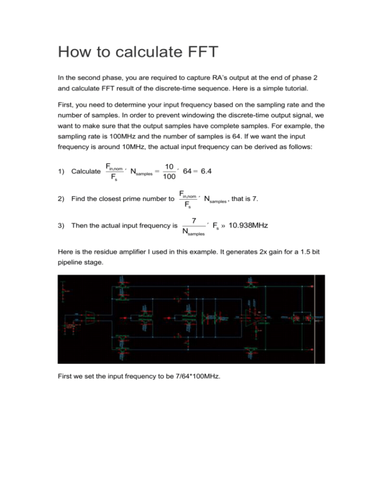
How to calculate FFT In the second phase, you are required to capture RA’s output at the end of phase 2 and calculate FFT result of the discrete-time sequence. Here is a simple tutorial. First, you need to determine your input frequency based on the sampling rate and the number of samples. In order to prevent windowing the discrete-time output signal, we want to make sure that the output samples have complete samples. For example, the sampling rate is 100MHz and the number of samples is 64. If we want the input frequency is around 10MHz, the actual input frequency can be derived as follows: Fin,nom ´ Nsamples = 10 ´ 64 = 6.4 100 1) Calculate 2) Find the closest prime number to 3) Then the actual input frequency is Fs Fin,nom Fs ´ Nsamples , that is 7. 7 Nsamples ´ Fs » 10.938MHz Here is the residue amplifier I used in this example. It generates 2x gain for a 1.5 bit pipeline stage. First we set the input frequency to be 7/64*100MHz. Since the SC CMFB settles in around 200 ns and we need 64 samples in total for FFT calculation, the stop time for transient simulation is set to be 200ns+64*10ns = 840ns. After simulation is finished, we could check the common mode output voltage. In my simulation, the non-overlapping time between phase 1 and phase 2 is 500ps. Phase 2 always ends at (n*10+9.75) ns, so the first sample is at 209.75 ns. We could use value() function to sample the residue amplifier output. Generate table from data. Save the data table as csv file: samples.csv. Then we could run matlab program on csv file to calculate FFT result of sampled RA output. 1) Use csvread to import data Make sure you have 64 samples in total. If you have more samples in you csv file, you should truncate them. 2) Then run prettyFFT on imported data. You could get 0 SNDR = 47.14dB -10 -20 -30 SFDR = 47.62dB THD = -47.14dB -40 3 -50 5 -60 -70 -80 7 9 -90 -100 -110 1 2 3 4 5 x 10 7 The full prettyFFT function is: [ENOB, SNDR, SFDR, SNR] = prettyFFT(wave,f_S,maxh,no_annotation,no_plot) 'wave' can be any length but should be coherently sampled (required) 'f_S' is the SAMPLING rate (i.e. f_Nyquist * 2) (optional, default = 1) 'maxh' is the highest harmonic plotted, 0 means all harmonics (optional, default = 12) NOTE: lowering this value will affect SNR since SNR is calculated as SNDR with harmonics removed. Setting maxh to 1 will effectivly set SNR = SNDR. (1 means only the fundamental is a 'harmonic') 'no_annotation' set to anything but 0 to turn off annotation (optional, default = 0) 'no_plot' set to anything but 0 to not create a plot (optional, default = 0) 'baseline' is the minimum value on the y-axis. When set to '0' the y-axis is auto-scaled such that some of the noise floor is displayed. It is useful to set this parameter when comparing two FFT plots by keeping the scale the same. (optional, default = 0)

![[#DTC-130] Investigate db table structure for representing csv file](http://s3.studylib.net/store/data/005888493_1-028a0f5ab0a9cdc97bc7565960eacb0e-300x300.png)
