SupplementalMaterial
advertisement
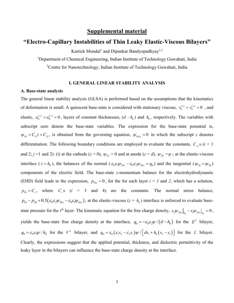
Supplemental material “Electro-Capillary Instabilities of Thin Leaky Elastic-Viscous Bilayers” Kartick Mondal1 and Dipankar Bandyopadhyay1,2 1 Department of Chemical Engineering, Indian Institute of Technology Guwahati, India 2 Centre for Nanotechnology, Indian Institute of Technology Guwahati, India I. GENERAL LINEAR STABILITY ANALYSIS A. Base-state analysis The general linear stability analysis (GLSA) is performed based on the assumptions that the kinematics of deformation is small. A quiescent base-state is considered with stationary viscous, v0( x ) v0( z ) 0 , and elastic, u0( x ) u0( z ) 0 , layers of constant thicknesses, (d – h0 ) and h0 , respectively. The variables with subscript zero denote the base-state variables. The expression for the base-state potential is, i 0 C1i z C2i , is obtained from the governing equation, i 0 zz 0 in which the subscript z denotes differentiation. The following boundary conditions are employed to evaluate the constants, C ji s (i = 1 and 2; j =1 and 2): (i) at the cathode (z = 0), 10 = 0 and at anode (z = d), 20 = ; at the elastic-viscous interface ( z h0 ), the balances of the normal ( 01 10 z 0 2 20 z q0 ) and the tangential ( 10 20 ) components of the electric field. The base-state z-momentum balance for the electrohydrodynamic (EHD) field leads to the expression, pi 0 z 0 , for the for each layer i = 1 and 2, which has a solution, pi 0 Ci , where Ci s (i = 3 and 4) are the constants. The normal stress balance, p10 p20 0.5 0 2 20 z 01 10 z , at the elastic-viscous (z = h0 ) interface is enforced to evaluate basestate pressure for the ith layer. The kinematic equation for the free charge density, s2 20 z h0 s1 10 z h0 0, yields the base-state free charge density at the interface, q0 0 2 / d h0 for the E L bilayer, q0 01 / h0 for the V L bilayer, and q0 0 1s2 2 s1 / ds1 h0 s2 s1 for the L bilayer. Clearly, the expressions suggest that the applied potential, thickness, and dielectric permittivity of the leaky layer in the bilayers can influence the base-state charge density at the interface. 1 B. Perturbed-state analysis The governing equations and the boundary conditions shown in the previous section are perturbed through the normal linear modes, u ue t i kx , v ve t i kx , i i 0 i e t i kx , pi pi 0 pi e t i kx , h h0 h e t i kx , and q q0 q e t i kx , where the symbols and k represent the linear growth coefficient and the wave number of the disturbance, respectively. The tilde symbols denote the perturbed variables. The linearized Laplace equation for the ith layer is, izz k 2 i 0 . (1) The general solution of Eq. (1) is, i D1i e kz D2i e kz . (2) Here the coefficients D ji (i = 1, 2 and a; j = 1 and 2) are constants. The constants D ji s can be evaluated by employing the linearized perturbed boundary conditions: (i) at the cathode (z = 0), 1 0 and anode (z = d), 2 0 ; (ii) at the elastic-viscous interface (z = h0 ), the normal [ 01 1z 0 2 2 z q ] and the tangential [ 1 2 h 10 z 20 z 0 ] component balances of the electric field. The subscript z in these expressions denotes differentiation The linearized forms of the governing Eqs. (2.1) and (2.2) in the main manuscript for the elastic film are, ikp1 G u zz( x ) k 2u ( x ) 0 , (3) p1z G u zz( z ) k 2u ( z ) 0 , (4) iku ( x ) u z( z ) 0 . (5) The linearized forms of the governing Eqs. (2.3) and (2.4) in the main manuscript for the viscous film are, ikp2 vzz( x ) k 2 v ( x ) 0 , (6) p2 z vzz( z ) k 2 v ( z ) 0 , (7) ikv ( x ) vz( z ) 0 . (8) Eliminating pi from the linearized governing Eqs. (3) – (5) and (6 – (8) results in the following biharmonic equations for the elastic and the viscous layers, (z) u zzzz 2k 2u zz( z ) k 4u ( z ) 0 , (9) 2 (z) vzzzz 2k 2 vzz( z ) k 4 v ( z ) 0 . (10) The general solutions for the Eqs. (9) and (10) are, u ( z ) ( A1i B2i z ) e kz ( A3i A4i z ) e kz , (11) v ( z ) ( B1i B2i z ) e kz ( B3i B4i z ) e kz . (12) Here the coefficients A ji and B ji (i = 1 and 2; j =1 to 4) are constants. The following are the linearized no slip and impermeability conditions at z = 0, u( x) u( z) 0 . (13) The linearized continuity of velocities, the tangential and normal stress balances, and the kinematic conditions at z = h reduce to the forms, u ( x ) v ( x ) and u ( z ) v ( z ) , (14) G uz( x ) iku ( z ) vz( x ) ikv ( z ) ikq0 2 h 20 z 0 , (15) p1 p2 2Guz ( z ) 2vz ( z ) 0 2 20 z 2 z 1 10 z 1z k 2 h 0 , (16) h u( z) , (17) q 1 s2 2 z s1 1z ikq0u ( x) . (18) The linearized tangential and normal stress balances, and the kinematic conditions at z = d, v ( x) v ( z) 0 . (19) The solutions for u ( z ) and v ( x ) , Eqs. (11) and (12), are used to obtain expressions for the linearized variables, u ( x ) , v ( x ) , and pi , form the linear continuity and x-momentum balance equations. The expressions for u ( x ) , u ( z ) , v ( x ) , v ( z ) and pi are then replaced in the linear boundary conditions, Eqs. (13 – 19) to obtain a set of homogeneous linear algebraic equations with eight unknown constants, A ji and B ji (i = 1 and 2; j = 1 to 4). Equating the determinant of the coefficient matrix to zero leads to the dispersion relation, f k , which is solved analytically with the help of the commercial package Mathematica™. The critical parameters are obtained by enforcing the neutral stability condition, 0 , in the dispersion relation and then solving the algebraic equation for kc and c . The dominant growth coefficient ( m ) and the corresponding wavelength ( m ) are evaluated by finding out the global maxima of . 3
![[ ] φ γ](http://s2.studylib.net/store/data/013475720_1-a3046763ec3921c9822635b17e2b0033-300x300.png)
