Coupled Pendula with Cobra3
TEP
Related topics
Spiral spring, gravity pendulum, spring constant, torsional vibration, torque, beat, angular velocity, angular acceleration, characteristic frequency.
Principle
Two equal gravity pendula with a particular characteristic frequency are coupled by a “soft” spiral spring.
The amplitudes of both pendula are recorded as a function of time for various vibrational modes and different coupling factors using a y/t recorder. The coupling factors are determined by different methods.
Equipment
2 Pendulum w. recorder connection
1 Helical spring, 3 N/m
1 Rod with hook
1 Weight holder f. slotted weights
5 Slotted weight, 10 g, black
2 Capacitor, 10 mF/35 V
1 Cobra3 Basic Unit
1 Power supply 12 V
1 Cobra3 Universal writer software
1 RS 232 data cable
1 Power supply 0-12 V DC/6 V, 12 V AC
2 Bench clamp -PASS2 Support rod -PASS-, square, l = 630 mm
2 Right angle clamp -PASS1 Measuring tape, l = 2 m
4 Connecting cord, l = 1000 mm, red
4 Connecting cord, l = 1000 mm, blue
PC, WindowsR 95 or higher
02816.00
02220.00
02051.00
02204.00
02205.01
39105.28
12150.00
12151.99
14504.61
14602.00
13505.93
02010.00
02027.55
02040.55
09936.00
07363.01
07363.04
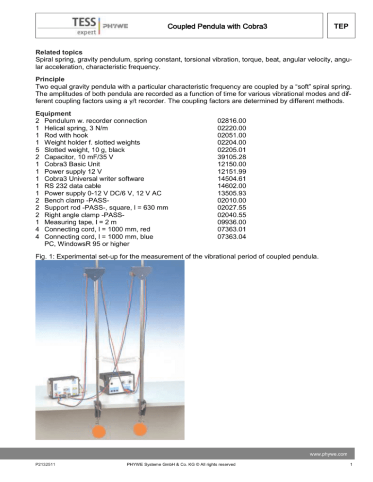
Fig. 1: Experimental set-up for the measurement of the vibrational period of coupled pendula.
www.phywe.com
P2132511
PHYWE Systeme GmbH & Co. KG © All rights reserved
1
TEP
Coupled Pendula with Cobra3
Tasks
1. To determine the spring constant of the coupling spring.
2. To determine and to adjust the characteristic frequencies of the uncoupled pendula.
3. To determine the coupling factors for various coupling-lengths using
a) the apparatus constants
b) the angular frequencies for “- inphase” and “in opposite phase” vibration
c) the angular frequecies of the beat mode.
4. To check the linear relation between the square of the couplinglengths and
a) the particular frequencies of the beat mode
b) the square of the frequency for “in opposite phase” vibration.
5. To determine the pendulum’s characteristic frequency from the vibrational modes with coupling and to
compare this with the characteristic frequency of the uncoupled pendula.
Set-up and procedure
Before measurement can begin, the exact value of the spring constant DF of the coupling spring has to
be determined. A supporting rod is fixed to the edge of table by means of a bench clamp. The spring is
suspended on the rod from a hook which is attached to the supporting rod via a right angle clamp. Applying Hook’s law
𝐹 = −𝐷𝐹𝑋
the spring constant 𝐷𝐹 can be calculated if the extension 𝑥 of the spring is measured for different slotted
weights attached to the spring.
The pendula are then set up without coupling springs as shown in Fig. 1. The input sockets of the pendula are now switched in parallel to the DC-output of the power supply unit. The yellow output sockets of
the pendula are connected to the Cobra3. The DC-output voltage of the power supply unit is adjusted to
10 V. For the channels CH 1 and CH 2, a value of 10 V is selected as the measuring range on the Cobra3.
To set the pendula into vibration the pendula rods are touched with the finger-tips on their upper third
and simultaneously moved to and fro till the desired amplitudes have been established. In this way
transverse vibrations can be avoided. In view of the subsequent experiments with coupled pendula
care should be taken already at this stage to ensure that the pendula are oscillating in the same plane.
From the plotted curves the period 𝑇0 is determined several times for each pendulum. The mean values
of the periods, 𝑇̅0 , of both pendula have to be identical within the limits of error. If deviations are observed, the lengths of the pendulum rods have to be adjusted. This is done by detaching the counter nut
on the threaded rod of the pendulum weight, adjusting the pendulum length and manually retightening
the counter nut.
For the performance of the experiments with coupled pendula, the coupling spring is fixed to the plastic
sleeves on the pendulum rods at a point equidistant from the pendulum’s fulcrum. Furthermore the “zero”-positions have to be readjusted. It has to be insured that there is no electric conductivity between the
pendula.
The amplitudes as a function of time are to be recorded for different coupling lenghts l using the following
initial conditions:
2
PHYWE Systeme GmbH & Co. KG © All rights reserved
P2132511
Coupled Pendula with Cobra3
TEP
A Both pendula are deflected with the same amplitude to the same side and simultaneously released.
(“in- phase” vibration)
B. Both pendula are deflected with the same amplitude but in opposite directions and simultaneously released. (“in opposite phase” vibration)
C. One pendulum remains at rest. The second pendulum is deflected and released (beat mode). Here
satisfactory results can only be achieved if during the preparation both pendula have been properly adjusted in such a way that they have in fact the same period 𝑇̅0 .
In all three cases the vibrations have to be recorded for at least three or four minutes. From the plotted
curves the mean values for the corresponding vibrational periods can be determined.
Setting of the Cobra3 basic unit
— Connect the recorder outputs of the pendula to the analog inputs of the Cobra3 basic unit. The signals
that are to measure in this experiment are rather slow. To reduce the sensitivity to the fast noise signals
use the 10 μF capacitors at the analog inputs of the Cobra3 basic unit.
— Connect the COBRA3 Basic Unit to the computer port COM1, COM2 or to USB port (use USB to
RS232 Adapter 14602.10). Start the measure program and select Cobra3 Universal Writer Gauge.
— Begin recording the measured values using the parameters given in Fig. 2.
Fig. 2: Measuring parameters
www.phywe.com
P2132511
PHYWE Systeme GmbH & Co. KG © All rights reserved
3
TEP
Coupled Pendula with Cobra3
Theory and evaluation
If two gravity pendula P1 and P2 with the same angular characteristic frequency W0 are coupled by a
spring, for the position of rest and small angle deviation ~ due to the presence of gravity and springtension we have the following torques (Fig. 3):
torque due to gravity:
𝑀𝑠,0 = 𝑚 𝑔 𝐿 𝑠𝑖𝑛 ϕ0 ~ 𝑚 𝑔 𝐿 𝜙0
(1)
torque due to spring-tension:
𝑀F,0 = − 𝐷F 𝑥0 𝑙 cos 𝜙0 ~ − 𝐷F 𝑥0 𝑙
𝐷F
𝑥0
𝑙
𝑚
𝐿
𝑔
𝜙0
= spring constant
= extension of the spring
= coupling length
= pendulum mass
= pendulum lengh
= acceleration due to gravity
= angle between the vertical and the position of rest
If 𝑃1 is now deflected by 𝜙1 and 𝑃2 by 𝜙2 (see Fig. 3) and subsequently released, we have because of
𝐼 𝜙̈ = 𝑀
𝐼 = moment of inertia of a pendulum around its fulcrum
𝐼 𝜙1̈ = 𝑀1 = −𝑚𝑔𝐿𝜙1 + 𝐷F 𝑙 2 (𝜙2 − 𝜙1 )
(2)
𝐼 𝜙2̈ = 𝑀2 = −𝑚𝑔𝐿𝜙2 + 𝐷F 𝑙 2 (𝜙2 − 𝜙1 )
Introducing the abbreviations
𝜔02 =
𝑚𝑔𝐿
𝐼
and Ω2 =
𝐷F 𝑙 2
𝐼
(3)
we obtain from Eqs. (2)
𝜙̈1 + 𝜔02 𝜙2 = − Ω2 (𝜙2 - 𝜙1 )
(4)
𝜙̈2 + 𝜔02 𝜙2 = + Ω2 (𝜙2 - 𝜙1 )
At 𝑡 = 0 the following three initial conditions are to be realized successively.
A: “inphase” vibration
𝜙1 = 𝜙2 = 𝜙𝐴 ; 𝜙1 − 𝜙2 = 0
B: “in opposite phase” vibration
− 𝜙1 = 𝜙2 = 𝜙𝐴 ; 𝜙1 − 𝜙2 = 2𝜙𝐴
4
(5)
PHYWE Systeme GmbH & Co. KG © All rights reserved
P2132511
Coupled Pendula with Cobra3
TEP
C: beat mode
𝜙1 = 𝜙𝐴 ; 𝜙2 = 0; 𝜙1 − 𝜙2 = 𝜙𝐴
The general solutions of the system of differential equations (4) with the initial conditions (5) are:
A:
𝜙1 (𝑡) = 𝜙2 (𝑡) = 𝜙𝐴 𝑐𝑜𝑠 𝜔0 𝑡
(6a)
B:
𝜙1 (𝑡) = 𝜙𝐴 cos ( √𝜔02 + 2 Ω2 𝑡)
(6b)
𝜙2 (𝑡) = − 𝜙𝐴 cos ( √𝜔02 + 2 Ω2 𝑡)
C:
𝜙1 (𝑡) = 𝜙𝐴 cos (
. cos (
√𝜔02 +2 Ω2 − 𝜔0
√𝜔02 +2 Ω2 + 𝜔0
2
𝜙2 (𝑡) = − 𝜙𝐴 sin (
. sin (
2
. 𝑡)
. 𝑡)
√𝜔02 +2 Ω2 − 𝜔0
2
√𝜔02 +2 Ω2 + 𝜔0
2
(6c)
. 𝑡)
. 𝑡)
Comment
A: “inphase” vibration
Both pendula vibrate inphase with the same amplitude and with the same frequency vg. The latter is
identical with the angular characteristic frequency v0 of the uncoupled pendula.
𝜔𝑔 = 𝜔0
(7a)
www.phywe.com
P2132511
PHYWE Systeme GmbH & Co. KG © All rights reserved
5
TEP
Coupled Pendula with Cobra3
B: “in opposite phase” vibration
Both pendula vibrate with the same amplitude and with the same frequency vc but there is a phasedifference of p. In accordance with (3), the angular frequency
𝜔𝑐 = √𝜔02 + 2 Ω2
(7b)
depends on the coupling length 𝑙.
C: Beat mode
For weak coupling, e.g. 𝜐0 ⪢ Ω, the angular frequency of the first factor can be expressed as follows:
𝜔1 =
√𝜔02 +2 Ω2 − 𝜔0
2
≃
Ω2
2𝜔0
(8a)
For the angular frequency of the second factor we get:
𝜔2 =
√𝜔02 +2 Ω2 + 𝜔0
2
≃ 𝜔0 +
Ω2
2𝜔0
(8b)
Subsequently we get:
𝜔1 < 𝜔2
Fig. 4 shows the amplitudes 𝜙1 (𝑡) and 𝜙2 (𝑡) of both pendula as a function of time for the beat case and
for different coupling lengths 𝑙. As coupling factor we define the ratio
𝐾=
𝐷F 𝑙 2
𝑚𝑔𝐿+ 𝐷F 𝑙 2
(9)
From Eq. (3) and Eq. (9) we get
Ω2
𝐾 = 𝜔 2 + Ω2
(10)
0
The coupling factor 𝐾 of Eq. (10) can be calculated from the frequencies of the individual vibrational modes.
Substituting Eq. (7a) and Eq. (7b) into Eq. (10) results in
𝜔2 −𝜔2
𝐾 = 𝜔𝑐2 +𝜔𝑔2
𝑐
(11)
𝑔
(“in opposite phase” vibration)
6
PHYWE Systeme GmbH & Co. KG © All rights reserved
P2132511
Coupled Pendula with Cobra3
TEP
𝑙 = 30 cm
𝑙 = 60 cm
𝑙 = 90 cm
Fig. 4: Amplitude curves of the vibrations of coupled pendula in the beat mode for three different coupling lengths 𝑙
(30 cm, 60 cm and 90 cm) as a function of time.
www.phywe.com
P2132511
PHYWE Systeme GmbH & Co. KG © All rights reserved
7
TEP
Coupled Pendula with Cobra3
Substituting Eq. (8a) and Eq. (8b) into Eq. (10) yields:
2𝜔 𝜔
𝐾 = 𝜔2 +1 𝜔2
1
(12)
2
(beat case)
To check the influence of coupling length on the frequencies of the individual vibrational modes, we substitute Eq. (11) and Eq. (12) into Eq. (9). Then we get for the in opposite phase
vibration:
𝜔12 =
2𝐷F 𝜔02
𝑚𝑔𝐿
𝑙 2 + 𝜔02
(13)
And for the beat mode:
𝐷
F
𝜔1 = 𝜔0 2𝑚𝑔𝐿
𝑙2
(14)
as well as
𝜔2 = 𝜔 0
𝐷F
2𝑚𝑔𝐿
𝑙 2 + 𝜔0
(15)
The measurement of the “inphase” vibration of the uncoupled pendula results in the following:
𝑇0 = (2.036 ± 0.003)s;
or
2𝜋
𝑇0
∆𝑇0
𝑇0
≈ ±0.15 %
(16)
= 𝜔0 = (3.083 ± 0.005) 𝑠 −1
Analysis of the measurement
For the analysis of the results select the following parameters:
In the “Analysis” / “Channel modification” window (see Fig. 5) select:
source channel:
Operation:
Destination channel:
Title:
Symbol:
Unit:
Time
f : = x/1000
overwrite / Time
Time_in_seconds
t
s
Fig. 5: Channel modification.
8
PHYWE Systeme GmbH & Co. KG © All rights reserved
P2132511
Coupled Pendula with Cobra3
TEP
To determine the frequency of the in opposite phase vibration select in the “Analysis” window the option
“Fourier analysis” for the measured channel (see Fig. 6):
Fig. 6: Fourier analysis of the in opposite phase vibration.
With the function “Survey” determine then the frequency 𝑓𝑐 (see Fig. 7). In our example 𝑓𝑐 = 0.571 Hz for
the coupling length 𝑙 = 80 cm and 𝜔𝑐 = 2𝜋𝑓𝑐 = 3.580 1/𝑠.
www.phywe.com
P2132511
PHYWE Systeme GmbH & Co. KG © All rights reserved
9
TEP
Coupled Pendula with Cobra3
Fig. 7: Determination of the frequency of the in opposite phase vibration.
With the same procedure (“Analysis” / “Fourier analysis” / “Survey” function) determine the frequencies
𝜔1 and 𝜔2 for the beat case. In our example (see Fig. 8) we obtain for the coupling length =
90 𝑐𝑚: 𝑓1 = 0.099 Hz, 𝜔1 = 𝜋 𝑓1 = 0.311 1/𝑠 and 𝜔2 = 𝜔1 + 2𝜋 𝑓0 = 3.401 1/𝑠, with 𝑓0 = 0.491 Hz.
Fig. 8: Determination of the frequencies v1 and v2 for the beat mode.
10
PHYWE Systeme GmbH & Co. KG © All rights reserved
P2132511
Coupled Pendula with Cobra3
TEP
Tab. 1 shows the mean values of the vibrational periods for different coupling lengths l as well as the
corresponding angular frequencies.
From the measured values of the “inphase” vibration we get
𝑇𝑔 ⩠ (2.033 ± 0.004)𝑠;
or
2𝜋
𝑇0
∆𝑇0
𝑇0
≈ ± 0.2 %
= 𝜔0 = (3.090 ± 0.006) s −1
Fig. 9: Frequency of the opposite phase vibration 𝜔𝑐2 as a function of the coupling length 𝑙 2 .
www.phywe.com
P2132511
11
PHYWE Systeme GmbH & Co. KG © All rights reserved
TEP
Coupled Pendula with Cobra3
We used:
𝐷F=3.11 N/m (measured value)
𝐿 = 𝐿1 = 𝐿2 = 101.5 𝑐𝑚
(distance fulcrum center of pendulum weight)
𝑚 = 1 kg
(mass of pendulum rod is not included)
𝑔 = 9.81 m/s
In Fig. 9 the measured values ω2c of Tab. 1 have been plotted versus l2 . From the regressive line
y = A + Bx
we obtain
𝐴 = (9.65 ± 0.58)𝑠 −2 ;
∆𝐴
𝐴
= ±6 %
∆𝐵
𝐵 = (4.81 ± 0.14)𝑠 −2 𝑚−2 ;
= ±3 %
𝐵
Comparison with Eq. (13) gives
√𝐴 = 𝜔0 = (3.106 ± 0.093) 𝑠 −1;
∆𝜔0
𝜔0
= ±3 %
In Fig. 10 the measured values 𝜔2 of Tab. 1 have been plotted versus 𝑙2 . The regression line
𝑦 = 𝐴 + 𝐵𝑥
should confirm Eq. (15). We obtain:
𝐴 = 𝜔0 = (3.099 ± 0.009)s−1 ;
𝐵 = (0.374 ± 0.015)s −1 𝑚−2 ;
12
∆𝜔0
=±3%
𝜔0
∆𝐵
=±4%
𝐵
PHYWE Systeme GmbH & Co. KG © All rights reserved
P2132511
Coupled Pendula with Cobra3
TEP
Fig. 10: Frequency 𝜔2 (beat mode) as a function of the coupling length 𝑙 2 .
In Fig. 11 the measured values 𝜔1 of Tab. 1 are plotted as a function of 𝑙 2 . The regression line 𝑦 =
𝐵𝑥 through the origin confirms Eq. (14), 𝐵 = (0.374 ± 0.015) 1/𝑠 2 𝑚2.
The results obtained for 𝜔0 using three different vibrational modes for the coupled pendula are in good
agreement with the angular characteristic frequency of the uncoupled pendula.
Fig. 11: Frequency 𝜔1 (beat mode) as a function of the coupling length 𝑙 2 .
www.phywe.com
P2132511
13
PHYWE Systeme GmbH & Co. KG © All rights reserved


