Quantum Eraser
TEP
2.2.0800
Safety tip
Related Topics
Wave-particle duality, wave interference, quantum mechanics.
Principle
A Mach-Zehnder-interferometer is illuminated with a laser beam. Circular interference fringes
appear on the screens behind the interferometer. If polarization filters with opposite polarization planes
are placed in the two interferometer paths the interference patterns disappear. Placing another polarizer
before one of the screens causes the pattern to reappear. Electromagnetic radiation can be described
both in terms of propagating waves, as well as particles (photons). The experiment illustrates this duality
by showing how interference patterns can be explained on the basis of both classical wave mechanics
and quantum physics.
Equipment
1
Base plate in experimental case
1
Laser, Helium-Neon, 0.2/1.0 mW
4
Surface mirror
4
Adjusting support
2
Beam splitter 50 % : 50%
2
Holder for diaphragm/beam splitter
2
Screen 150 mm × 150 mm
1
Glass lens in mounting, f = +20 mm
1
Lens holder for base plate
1
Polarization specimen, mica
1
Diaphragm holder for base plate
3
Polarisation filter for base plate
13 Magnetic foot for base plate
08700-01
08180-93
08711-01
08711-00
08741-00
08719-00
09826-00
08018-01
08723-00
08664-00
08724-00
08730-00
08710-00
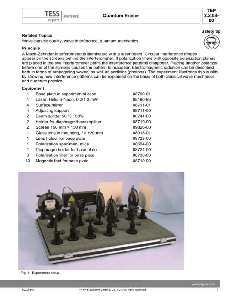
Fig. 1: Experiment setup.
www.phywe.com
P2220800
PHYWE Systeme GmbH & Co. KG © All rights reserved
1
TEP
2.2.0800
Quantum Eraser
Caution!
Laser radiation! DO NOT STARE into the beam or view directly with optical instruments! Wear protective
goggles!
Tasks
1. Set up the experiment and observe the interference pattern on the screen.
2. Change the polarization of the beams with the PF1 and PF2 polarizers and observe the influence
on the interference pattern.
3. Use the third polarizer PF3 to cancel the polarization of the light in the two beams, and observe
the reappearance of the interference pattern.
Set-up and Procedure
In this experiment a Mach-Zehnder Interferometer is
used to split a light beam into two parts, send them
along two different paths where they can be subjected to individual treatment and then to reunify the two
beams again and observe interference effects (See
Fig.2). Since the precise alignment of the Interferometer is crucial the individual steps will be described
in the following and illustrated with photographs. In
the final set-up shown in Fig. 3 the position of all the
optical elements can been seen along with the names
and abbreviations used for them in this set-up guide.
Fig. 2: Schematic diagram of the optical paths.
Fig. 3: Final setup.
2
PHYWE Systeme GmbH & Co. KG © All rights reserved
P2220800
Quantum Eraser
-
-
-
-
-
TEP
2.2.0800
Fix the laser (HeNe 0,2/1mW) to the optical
base plate so that the beam path height is
about 12,5 cm above the plate (Fig. 4).
Direct the beam with the mirror M1 to the right
corner in the front of the plate. Adjust the mirror
M1 so that the beam path height there is the
same as at the exit point of the laser (Fig. 5).
In this step the mirrors M2, M3, M4 and the
beam splitters BS1, BS2 will be preadjusted so
that the beam height can be maintained. To
achieve this, the respective elements are positioned in the right corner in the front of the
plate. Their height is adjusted so that the beam
coming from mirror M1 strikes them in the centre. The tilt should be adjusted so that the beam Fig. 4: Fixing the laser to the optical base plate.
is reflected onto itself (Fig. 6).
The mirrors M1, M2, M3, M4, the beam splitters
BS1, BS2 and the screens are positioned as
shown in Fig. 7 so that the indicated light-path
forms. One should make sure that the coated
side of the beam splitter BS1 is located on the
side pointing towards mirror M2 and the coated
side of beam splitter BS2 points toward mirror
M4.
The beams should preferably travel parallel to
the lines on the base plate and strike the optical
elements in the centre.
The goal of this step is to achieve a perfect coincidence of the pairs of beams going from the
beam splitter BS2 to the screens. For adjustment one uses the mirror M4 and the beam
splitter BS2.
Fig. 5: Directing the beam with the mirror M1 to the
One of the two screens should be quite close to right corner in the front of the plate.
the beam splitter BS2 the other one far away
(Fig. 8).
Fig. 6: Adjusting the mirrors M2, M3, M4 and the beam
splitters BS1, BS2.
Fig. 7: Correct set-up of the mirrors and the beam splitters.
www.phywe.com
P2220800
PHYWE Systeme GmbH & Co. KG © All rights reserved
3
TEP
2.2.0800
Quantum Eraser
Fig. 8: Adjusting the beams.
-
Initially on both screens two bright points will be visible. With the adjustment screws at mirror M4
these points can be brought to coincide on one of the two screens. But the adjustment is only done
when the points coincide on both screens (the close one and the far one) simultaneously. A twinkling of these points then already indicates interference effects. Typically the simultaneous coincidence of both pairs of points can not be realized with the adjustment screws on mirror M4 alone.
Additionally the mirror M4 has to be moved to the left or to the right to achieve this. If the two dots
appear in different heights on one of the screens while they coincide on the other one, this can be
corrected by tilting the beam splitter BS2.
-
The expansion lens (f = 20 mm) is brought into position. The interference pattern visible on both
screens should be centred with the aid of the adjustment screws of the mirror M4 (Fig.9).
Fig. 9: Centering the interference pattern
4
PHYWE Systeme GmbH & Co. KG © All rights reserved
P2220800
TEP
2.2.0800
Quantum Eraser
-
Now the λ ∕ 4 plate is brought into position. The
role of this plate is to transform the linear polarized laser light into circular polarized light. This
has the advantage that the orientation of the polarizers relative to the beam coming from the laser is of no importance.
Place the three polarizing filters PF1, PF2 and
PF3 as shown in Fig. 11 and Fig. 12.
Fig. 10: Set-up of the λ ∕ 4 plate.
To align the λ ∕ 4 plate correctly, place SC1
temporarily as shown in Fig. 10. With correct orientation, the intensity of the diffraction pattern
seen on screen 1 is regardless of the settings of
PF1. Finally, reset SC1.
-
Fig. 11: Complete experiment setup, side view.
Fig. 12: Complete experiment setup, top view.
www.phywe.com
P2220800
PHYWE Systeme GmbH & Co. KG © All rights reserved
5
TEP
2.2.0800
Quantum Eraser
Experiments
a) Qualitative investigation of interference
Having set the experiment as described above,
with the Mach-Zehnder setup the essential effects
of interference can be demonstrated impressively
and easily:
If you block one of the two paths in the interferometer, on the screens a relatively homogeneous spot
is visible. If you open now the blocked path, the
spot does not become brighter everywhere, but
there are regions (rings) where the brightness
drops. This means, adding light to more light can
result in darkness. If one blocks only half of one
path, direct comparison is possible as shown in Fig.
13 and Fig. 14.
Fig. 14: Pattern seen on the screen when blocking half
b) Analogy experiment to a quantum eraser
of the beam.
Shift the polarizing filter PF3 out of beam path. The
polarizing filters PF1 and PF2 are oriented so that
light passing them has the same polarization. Under these circumstances interference rings are visible
on both screens.
Fig. 13: Blocking half of the beam.
6
PHYWE Systeme GmbH & Co. KG © All rights reserved
P2220800
Quantum Eraser
TEP
2.2.0800
If you rotate PF1 so that light passing it is polarized perpendicular to light passing PF2 the interference
effect on both screens vanishes. The quantum mechanical reason for this is, that now one could in principle determine which path in the interferometer a photon took by analysing its polarisation after it left the
interferometer. The quantum information about the path of a photon, imposed upon it by the polarisors,
destroys its ability to interfere.
The next step is to introduce the polarizing filter PF3 and orientate it at an angle of 45 degrees with respect to PF1 and PF2. The interference pattern is visible again on the screen SC1 behind PF3 since it is
not possible any more by analysing the photons arriving there, to
determine which path they took in the interferometer.
The next step is to introduce the polarizing filter PF3 and orientate it at an angle of 45 degrees with respect to PF1 and PF2. The interference pattern is visible again on the screen SC1 behind PF3.
Theory and Evaluation
1. Classical physics - wave interference
Wave interference is the superposition of two or
more waves that results in a new wave pattern.
The resultant displacement at a point is equal to
the vector sum of the displacements of different
waves at that point. To illustrate this principle, let
us assume two sinusoidal waves of the same
wavelength interfere with each other. If the
phase-shift between them is zero, in other words,
if at any given point their amplitudes are the
same, the overall amplitude will be double that of
each wave (constructive interference). If, on the
other hand, their phases are shifted by half a period, they will cancel each other out (destructive
interference). Fig. 15 illustrates this example.
Most electromagnetic waves can be well approximated by plane waves, that is waves with infinite- Fig. 15: Illustration of wave interference.
ly long and wide wavefronts. For such electromagnetic waves, it follows from Maxwell’s equations that the electric and magnetic field are perpendicular to the direction of propagation and to each other.
Electromagnetic waves exhibit a property called polarization, which describes the orientation of their oscillations. Conventionally, when considering polarization, only the electric field vector is described and
the magnetic field is ignored, since it is perpendicular to the electric field and proportional to it. If we divide the electric field vector into x and y components, a polarization of a wave tells us how those components change in time. In other words, a polarization state of an electromagnetic wave is the shape traced
out in a fixed plane by the electric vector as such a plane wave passes over it (Fig. 16).
Important fact is that electromagnetic waves of different polarization do not interfere with each other.
The laser in the experiment produces coherent electromagnetic radiation, i.e. electromagnetic waves
with the same frequency, polarization and phase. The beam is split into two, and the polarization of each
beam can be changed separately by adjusting the polarizers PF1 and PF2. Hence, if we set the polarization of both beams to be the same (equivalent to removing the polarizes from the beam paths), we observe the interference pattern on the screens. The bright fringes are the locations where the incoming
beams interfere constructively, hence producing higher amplitude than without the interference effect,
while the dark fringes are the locations where destructive interference takes place, and the radiation from
the two beams cancels each other out. When we use the polarizers PF1 and PF2 to set different polarizations for each beam, the interference pattern disappears, since electromagnetic waves of different po-
www.phywe.com
P2220800
PHYWE Systeme GmbH & Co. KG © All rights reserved
7
TEP
2.2.0800
Quantum Eraser
Fig. 16: Schematic representation of electromagnetic waves and their
polarization.
larization do not interfere. We can now use the third polarizer, PF3, to recover the interference fringes by
setting it at an angle of 45° with respect to the polarizers PF1 and PF2. In doing so, we again bring the
two beams to the same polarization, and they interfere.
2. Quantum physics – the quantum eraser
The experiment can also be interpreted by a quantum theory. Hence, we now consider the electromagnetic radiation to consist of photons. Note, that this does not mean that we can think of photons as rigid
spheres. Actually, in mathematical terms, a state of a system (a photon for example) in quantum mechanics is described by a complex wave function Ψ(x,t) (also called a state vector in a complex vector
space), belonging to a complex separable Hilbert space, and is governed by the Schrödinger equation
(Eq. 1)
i
( x, t ) ( x, t )
t
(1)
where i is the complex number, ħ is the reduced Planck constant and Ĥ is the Hamiltonian operator.
The wave function Ψ(x,t) is a rather abstract mathematical object and does not represent an observable,
that is, a quantity we can actually measure. What we can obtain from the quantum theory is a probability
density of an observable, which is given by the amplitude of the wave function. Hence, we can calculate
the probability of finding a particle at a given position in space, or having a given momentum, or energy,
etc. Therefore, even though we talk about particles, the quantum theory describes them as wave packets, and what we actually obtain are “clouds” of probability. For example, if we calculate a position of a
photon, the result will be a region in space where the probability is non-zero, and not a single location,
as in classical physics. What this means is that, from the quantum point of view, the particle is everywhere in the region where the calculated probability is non-zero. Additionally, the probability is given
only by the amplitude of the wave function, while the phase encodes information about the interference
between quantum states. This gives rise to the wave-like behavior of quantum states. For example, if
there are two ways for a photon to travel, as in the quantum eraser experiment, and both are equally
probable (we cannot measure which path the photon actually takes), both of these quantum states interfere with each other and result in the fringe pattern we observe.
Contrary to classical mechanics, the quantum theory does not allow for accurate simultaneous predictions of conjugate variables, like position and momentum, time and energy (frequency). This is known as
the uncertainty principle (Eq. 2, for position and momentum)
8
PHYWE Systeme GmbH & Co. KG © All rights reserved
P2220800
Quantum Eraser
xp
2
TEP
2.2.0800
(2)
where Δx and Δp are the uncertainty of position and momentum, respectively. Hence, a minimum exists
for the product of the uncertainties, and the more precisely one property is measured, the less precisely
the other can be measured.
Now let us interpret the experiments using quantum physics. Even though the laser produces many photons that travel through the setup simultaneously, the truly amazing fact is that the result is the same
(interference pattern is formed) even when we sent one photon at the time. From the quantummechanical point of view, the photon has non-zero probabilities of travelling along both paths in the setup, therefore it travels simultaneously along both paths and interferes with itself ! Both states (photon travelling along path a and path b) coexist and have the same probabilities, and the wave function is
a superposition of those states, which results in the interference pattern. When we use the polarization
filters PF1 and PF2 to prescribe polarization information on the photon (opposite polarizations for each
path), the wave function changes (and hence the probabilities of finding the photon along the two paths)
and removes the ability of the photon to interfere with itself. What it means is that, by polarizing the photon, we are able to tell which path it travelled (the probability becomes one for one path and zero for the
other) and hence only one state exists. Thus the interference pattern disappears. When we erase the polarization information with the third polarizer (PF3), the probability of finding a photon at a given location
at the detector (screen) results again from a superposition of the two equally probable quantum states
(photon travelling along path a and path b), and hence forms the interference pattern. Thus the name
“quantum eraser”.
www.phywe.com
P2220800
PHYWE Systeme GmbH & Co. KG © All rights reserved
9
TEP
2.2.0800
10
Quantum Eraser
PHYWE Systeme GmbH & Co. KG © All rights reserved
P2220800

