Supporting information 1. Structure of organic dye D102 and spiro
advertisement
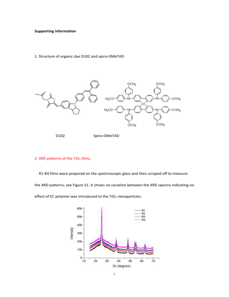
Supporting information 1. Structure of organic dye D102 and spiro-OMeTAD D102 Spiro-OMeTAD 2. XRD patterns of the TiO2 films. R1-R4 films were prepared on the spectroscopic glass and then scraped off to measure the XRD patterns, see Figure S1. It shows no variation between the XRD spectra indicating no effect of EC polymer was introduced to the TiO2 nanoparticles. 1 Figure S1. XRD patterns of TiO2 powders made from R1, R2, R3 and R4 pastes. 3. SEM surface morphologies of the four TiO2 films after TiCl4 post-treating. After the TiCl4 treatment, all the films are quite flat and homogeneous. Figure S2. SEM surface morphologies of the post-TiCl4 treated TiO2 films made from R1, R2, R3 and R4 pastes. 4. Porosity calculation from the optical reflectometry. The addition of EC polymer would not change the TiO2 particle crystal and size but only change the porosity of TiO2 films. Here we introduced the optical reflectometry to calculate the porosity of the TiO2 films as Docampo et al. reported. As shown in Figure S3, the 2 refractive index of the films (nfilm) was calculated by picking the two nearby peaks and determined by n1=1/[2d(1/λ1-1/λ2)]. In this way, series refractive indexes of the films were determined at different wavelengths. Afterwards, the Bruggeman’s mean field approximation (Equation 1) was introduced to calculate the air volume fraction (vair) in the TiO2 films, which in another word is the porosity of the films. Particularly, nTiO2 is the refractive index of pure TiO2, and at the wavelength of 600 nm, nTiO2=2.5. As a result, the calculated porosity of R1 to R4 films was 49%, 51%, 54% and 59%, respectively. To calculate the variation of vair, standard variations of the film thickness and the fitting of series refractive index of the films to the Cauchy’s relation (Equation 2) were counted. The final variation of vair for R1 to R4 films was about 2%. (1 vair ) n A 2 2 nTiO 2 n film 2 2 nTiO 2 2n film B 2 C 4 vair 1 n2film 1 2n2film 0 (1) .... (2) P. Docampo, A. Hey, S. Guldin, R. Gunning, U. Steiner, H.J. Snaith, Adv Funct Mater 22, 5010-5019 (2012). 3 Figure S3. Reflectance versus wavelength of TiCl4 post-treated mesoporous R3 film. 5. Preparation of Al2O3 paste. Nanoparticles of γ-Al2O3 (~ 50 nm) were utilized, and its paste was prepared as Ito et al. reported. To simplify, γ-Al2O3 was conjugated with ethyl cellulose (previously dissolved in ethanol at a weight ratio of 10 %) and terpineol, then the paste was concentrated by rotating evaporation. Finally, the paste was diluted by terpineol and spin-coated on the FTO glass at 2500 rpm for 30s. The resulting thickness of Al2O3 films was about 2 µm. S. Ito, T.N. Murakami, P. Comte, P. Liska, C. Gratzel, M.K. Nazeeruddin, M. Gratzel, Thin Solid Films, 516, 4613-4619 (2008). 4
